3.3 Connecting the Voltage Cords
42
The color and number of voltage cords to use depends on the wiring
configuration of the system being measured.Connect the supplied
Model L9438-55 Voltage Cord Set to the voltage input terminals on the
instrument.
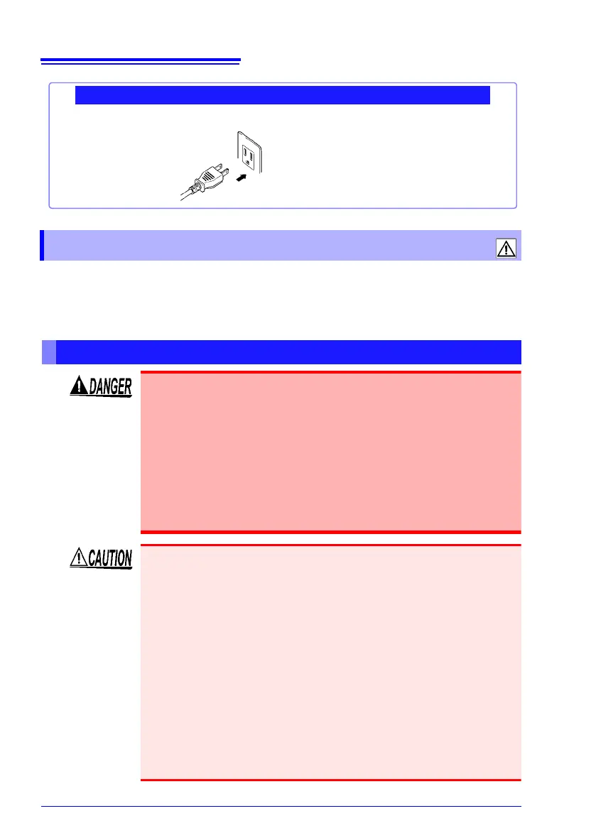
Grounded and Ungrounded Outlets
Plug the power cord
into the outlet
Using a Grounded Outlet
3.3 Connecting the Voltage Cords
Before Connecting
Connect the voltage cords to the instrument first, and then to the
active lines to be measured.
Observe the following to avoid electric shock and short circuits.
• Voltage cord should only be connected to the secondary side of
a
breaker, so the breaker can prevent an accident if a short cir-
cuit occurs. Connections should never be made to the primary
side of a breaker, because unrestricted current flow could cause
a serious accident if a short circuit occurs.
• Do not allow the voltage cord clips to touch two wires at the
same time. Never touch the edge of the metal clips.
• For safety reasons, when taking measurements, only use the L9438-
55 Voltage Cord set provided with the instrument. The supplied volt-
age cords are colored black. Do not connect any leads that are not
r
equired for a particular measurement.
• Removable caps are attached to the metal pins at the ends of the test
leads.
To prevent a short circuit accident, be sure to use the test leads with
t
he caps attached when performing measurements in the CAT III and
CAT IV measurement categories. The test leads can be used with the
caps removed when taking measurements in the CAT I and CAT II
measurement categories.
For details on measurement categories, see "Measurement catego-
ries"(p. 6).
• To prevent an electric shock accident, confirm that the white or red
por
tion (insulation layer) inside the cable is not exposed. If a color
inside the cable is exposed, do not use the cable.