3.3 Connecting the Voltage Cords
43
3
Removing the
caps
Gently hold the bottom of the caps and pull the caps off.
Safely store the removed caps so as not to lose them.
Attaching the
cap
s
Insert the metal pins of the test leads into the holes of the caps, and
firmly push them all the way in.
Example: TYPE 1
Removing and attaching the caps
The tips of the metal pins are sharp, so take care not to injure yourself.
Voltage Cord Connections
Insert the plugs into the terminals
as far as they will go.
Insert each voltage cord plug into
the terminal labeled with the corre-
sponding color.
Refer to "5.2 Connecting to the Lines to be Measured" (p. 81) regarding
measurement line wiring configuration diagrams.
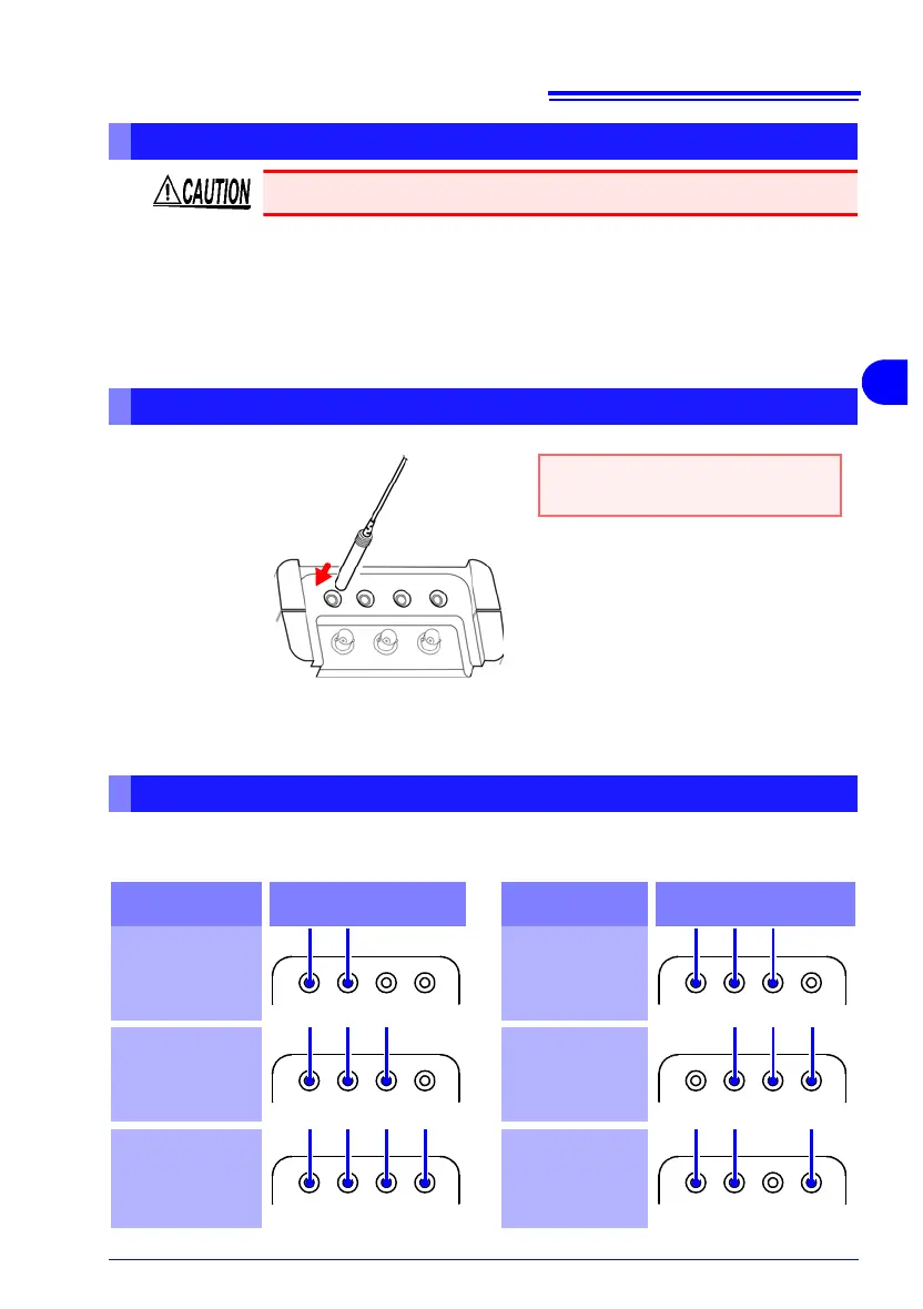
Voltage Input Terminals Wiring Diagrams
B: Black, R: Red, Y: Yellow, b: blue
Wiring
Configuration
Voltage Input Terminals
Wiring
Configuration
Voltage Input Terminals
Single-Phase
2-Wire
(1P2W)
Single-Phase
3-Wire
(1P3W)
Three-Phase
3-Wire
(3P3W2M)
Three-phase,
3-wire
(3P3W3M)
Three-Phase
4-Wire
(3P4W)
Three-Phase
4-Wire
2.5 Element
(3P4W2.5E)