[WIRING]
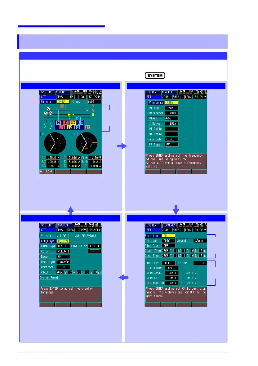
SYSTEM (Setting Conditions and System Settings)
The displayed screen changes each time you press
Correct
Wiring
Diagram
View the selected system wiring diagram while
connecting the voltage cords and clamp sen-
sors. Three-phase vectors and voltage, current
and power values can be verified. (p. 86)
Make basic settings for measurement. You can
set the measurement frequency, wiring config-
uration, clamp sensor model, current range, PT
and CT ratios.
Make recording-related settings here. You can
set memory partitioning, recording interval, de-
mand period, and enable/disable status and
threshold values for each type of event.
Make instrument-related system settings such
as display language, beep sounds, screen col-
ors, LCD backlight, LCD contrast, real-time
clock, phase names and phase colors.
The instrument’s version and serial No. are
also displayed.
Make the necessary settings before measuring.
[MEASURE]
[SYSTEM]
[REC&EVENT]
Event
Settings
Record-
ing Set-
tings
Connection
Check