3.4 Connecting Clamp Sensors
45
3
Example: TYPE 1
Before taking measurements, confirm that the clamp sensor model set-
ting is correct (p. 60)
.
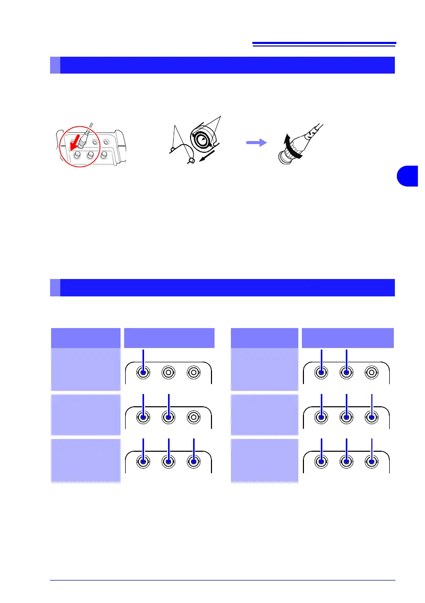
Clamp Sensor Connection Procedure
Connect each clamp sensor plug to the terminal labeled with the corresponding color.
Turn the plug clockwise to
lock.
To disconnect:
Push the plug in, turn it coun-
terclockwise to unlock, and
pull it out.
Lock
Notches in BNC Plug
(on clamp sensor cable)
BNC Jack Guide Pins
(on the instrument)
12
Align the notches in the BNC
plug with the guide pins on the
instrument's terminal, and
insert the plug.
Refer to "5.2 Connecting to the Lines to be Measured" (p. 81) regarding measure-
ment line wiring configuration diagrams.
Current Input Terminals Wiring Diagrams
R: Red, Y: Yellow, b: Blue
Wiring
Configuration
Current Input Terminals
Wiring
Configuration
Current Input Terminals
Single-Phase
2-Wire
(1P2W)
Single-Phase
3-Wire
(1P3W)
Three-Phase
3-Wire
(3P3W2M)
Three-phase,
3-wire
(3P3W3M)
Three-Phase
4-Wire
(3P4W)
Three-Phase
4-Wire
2.5 Element
(3P4W2.5E)