10.1 General Specifications
151
10
Chapter 10 Specifications
Accuracy
From 0.5 to 10 Hz, voltage, current and active power values are for relative comparison only
From 10 to 16 Hz and over 220 V, voltage and active power values are for relative comparison only
From 30 kHz to 100 kHz and over 750 V, voltage and active power values are for relative comparison only
From 100 kHz to 150 kHz and over 22000/f [kHz], voltage and active power values are for relative
comparison only
Over 1000 V, voltage and active power values are for relative comparison only
For current and active power measurements, combine the accuracy of the current sensor with the
above accuracies
Period of guaranteed accuracy 6 months (and 1.5 times specified accuracy for one year)
Conditions of Guaranteed Accuracy Temperature and humidity for guaranteed accuracy: 23±3°C, 80%RH or less
Warm-up time30 minutes or more
Input ....... Within the specified ranges when the fundamental wave is synchronized with the sync
source, for sine wave input, power factor of one, zero ground voltage, after zero adjustment
Temperature coefficient ±0.01%f.s./ °C (for DC, add ±0.01% f.s./°C)
Effect of common mode voltage ±0.01%f.s. or less (with 1000 V @50/60 Hz applied between voltage measurement jacks and chassis)
Magnetic field interference ±1%f.s. or less (in 400 A/m magnetic field, DC and 50/60 Hz)
Power factor influence ±0.15%f.s. or less (45 Hz to 66 Hz with power factor = 0.0)
with 500 Hz LPF, add ±0.45% f.s.
Susceptibility to conducted
electromagnetic field
@3 V, current and active power not more than ±6% f.s., where f.s. current is the rated primary-side
current of the current sensor
f.s. active power equals the voltage range × the rated primary-side current of the current sensor
Susceptibility to radiated
electromagnetic field
@10 V/m, current and active power not more than ±6% f.s., where f.s. current is the rated primary-
side current of the current sensor, and f.s. active power equals the voltage range × the rated primary-
side current of the current sensor
Effective measuring range Voltage, Current, Power..... 1% to 110% of the range
Total display area Voltage, Current, Power.....
Voltage, current and power: from zero-suppression range setting to 120%
Zero-suppression ranges Selectable OFF,0.1 or 0.5% f.s.
When OFF, non-zero values may be displayed even with no measurement input
Zero adjustment Voltage ±10%f.s., current ±10% f.s. with no more than ±4 mV zero-adjustment compensation
Waveform peak measurement
range
Within ±300% of each voltage and current range
Waveform peak measurement
accuracy
Within ±2% f.s. of voltage and current display accuracy
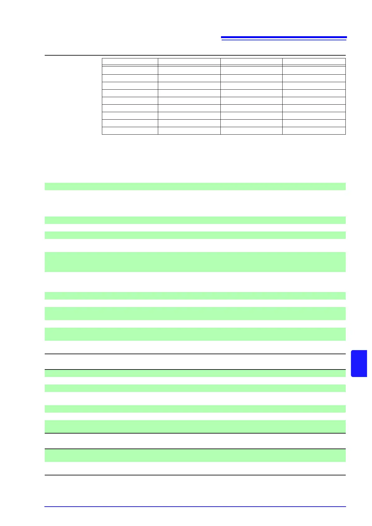
1.Power Measurement Input Specifications
Voltage(U) Current(I) Active power(P)
DC ±0.1%rdg.±0.1%f.s. ±0.1%rdg.±0.1%f.s. ±0.1%rdg.±0.1%f.s.
0.5 Hz to 30 Hz ±0.1%rdg.±0.2%f.s. ±0.1%rdg.±0.2%f.s. ±0.1%rdg.±0.2%f.s.
30 Hz to 45 Hz ±0.1%rdg.±0.1%f.s. ±0.1%rdg.±0.1%f.s. ±0.1%rdg.±0.1%f.s.
45 Hz to 66 Hz ±0.05%rdg.±0.05%f.s. ±0.05%rdg.±0.05%f.s. ±0.05%rdg.±0.05%f.s.
66 Hz to 1 kHz ±0.1%rdg.±0.1%f.s. ±0.1%rdg.±0.1%f.s. ±0.1%rdg.±0.1%f.s.
1 kHz to 10 kHz ±0.2%rdg.±0.1%f.s. ±0.2%rdg.±0.1%f.s. ±0.2%rdg.±0.1%f.s.
10 kHz to 50 kHz ±0.3%rdg.±0.2%f.s. ±0.3%rdg.±0.2%f.s. ±0.4%rdg.±0.3%f.s.
50 kHz to 100 kHz ±1.0%rdg.±0.3%f.s. ±1.0%rdg.±0.3%f.s. ±1.5%rdg.±0.5%f.s.
100 kHz to 150 kHz ±20%f.s. ±20%f.s. ±20%f.s.
2.Frequency Measurement Specifications
Measurement channels Four (f1 to f4)
Measurement source Select U/I for each measurement channel
Measurement method Reciprocal method + zero-crossing sample value correction
Measuring range Synchronous range from 0.5 Hz to 5 kHz (with 0.0000 Hz unmeasurable time)
Selectable lower limit measurement frequency (0.5 Hz, 1 Hz, 2 Hz, 5 Hz, 10 Hz, 20 Hz)
Data update interval 50 ms (measurement-frequency-dependent at 45 Hz and below)
Accuracy ±0.05% rdg. ±1 dgt. (sine wave, amplitude at least 30% of measurement range)
Numerical display format 0.5000 Hz to 9.9999 Hz, 9.900 Hz to 99.999 Hz, 99.00 Hz to 999.99 Hz,
0.9900 kHz to 5.0000 kHz
3.Integration Measurement Specifications
Measurement Mode Selectable RMS or DC for each wiring mode (DC is selectable only for 1P2W wiring and AC/DC sen-
sors)
Measurement items Current integration (Ih+, Ih-, and Ih), active power integration (WP+, WP-, and WP)
Ih+ and Ih- only for DC mode measurements, and lh only for RMS mode measurements