10.1 General Specifications
152
Measurement method Digital calculation from each current and active power phase (when averaging, calculates with pre-
vious average value)
In DC mode: calculates current value at every sample, and integrates instantaneous power indepen-
dent of polarity
In RMS mode: Integrates current effective values between measurement intervals, and polarity-in-
dependent active power value
Measurement Interval 50 ms data update interval
Display resolution 999999 (6 digits + decimal)
Measuring range 0 to ±9999.99 TAh / TWh (limited to maximum integration time of 9999 hours, 59 minutes, and 59
seconds)
Integration stops when either maximum integration value or time is exceeded.
Integration time accuracy ±50ppm±1dgt. (0°C to 40°C)
Integration accuracy ± (current and active power accuracy) ± integration time accuracy
Backup function Integration automatically resumes after power outages.
3.Integration Measurement Specifications
4.Harmonic Measurement Specifications
Number of measurement channels 4 Channels
Harmonic measurements not available for multiple systems with different frequencies.
Measurement items Harmonic rms voltage, harmonic voltage percentage, harmonic voltage phase angle, harmonic rms
current, harmonic current percentage, harmonic current phase angle, harmonic active power, har-
monic power percentage, harmonic voltage-current phase difference, total harmonic voltage distor-
tion, total harmonic current distortion, voltage imbalance, current imbalance
Measurement method Zero-crossing synchronous calculation (all channels in same window), with gap
Fixed 500 kHz/s sampling, after digital anti-aliasing filter
Equal thinning between zero crossings (with interpolation calculation)
Synchronization source U1 to U4, I1 to I4, External (with motor evaluation option installed and CH B set for pulse input), DC
selectable (50 or 100 ms)
FFT calculation word length 32 bits
Anti-aliasing filter Digital filter (variable according to sync frequency)
Windows Rectangular
Synchronization frequency range As specified for power measurements
Data update interval 50 ms (measurement-frequency-dependent at 45 Hz and below)
Phase zero adjustment Provided by key operation or external control command (only with external sync source)
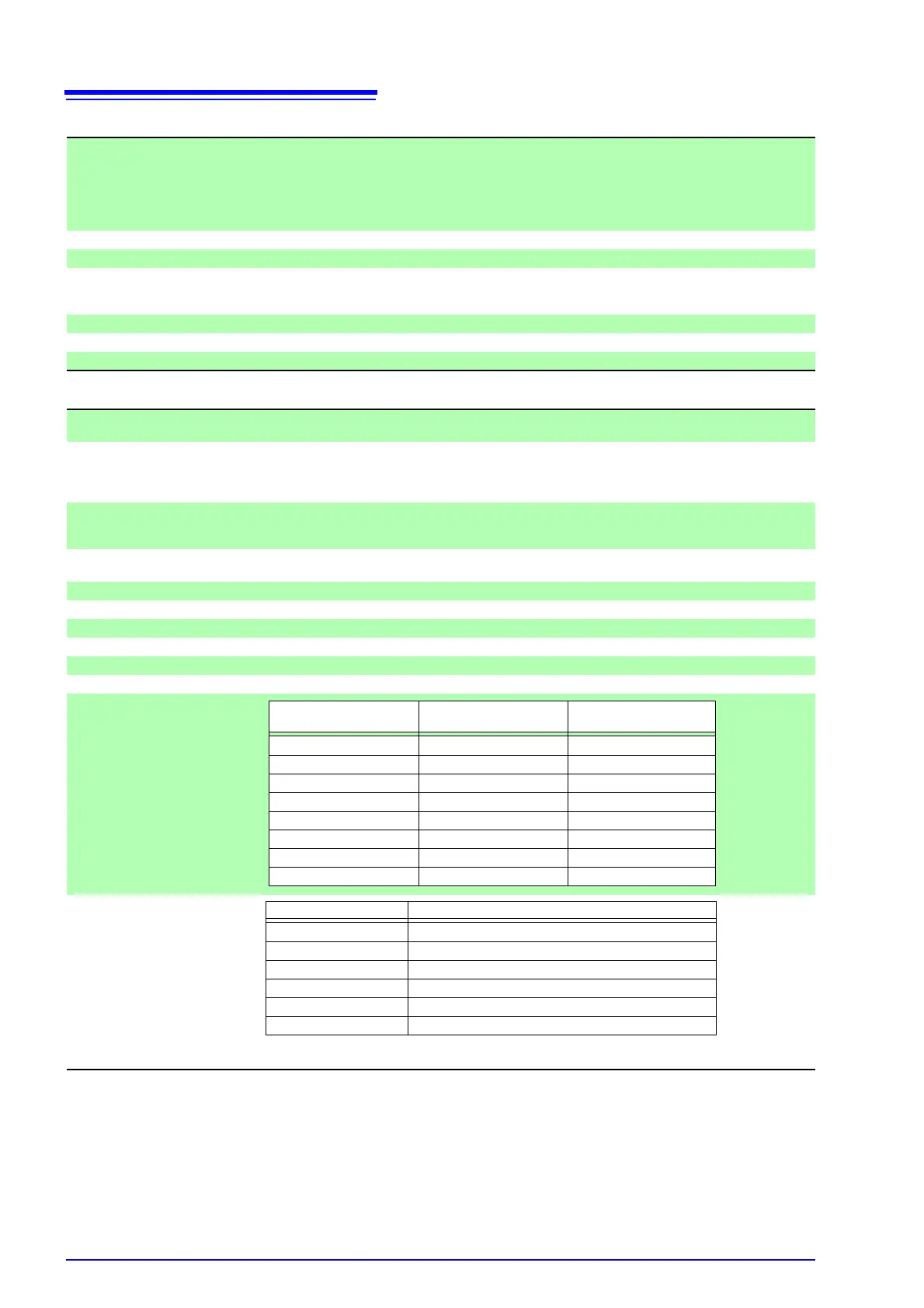
Highest order analysis
Accuracy
Not specified for sync frequencies of 4.3 kHz and higher
Add the LPF accuracy to the above when using LPF.
Synchronization frequency
range
Window waveforms Analysis order
0.5 Hz to 40 Hz 1 100
th
40 Hz to 80 Hz 1 100
th
80 Hz to 160 Hz 2 80
th
160 Hz to 320 Hz 4 40
th
320 Hz to 640 Hz 8 20
th
640 Hz to 1.2 kHz 16 10
th
1.2 kHz to 2.5 kHz 32 5
th
2.5 kHz to 5.0 kHz 64 3
th
Frequency Voltage(U), Current(I), Active Power(P)
0.5 Hz to 30 Hz ±0.4%rdg.±0.2%f.s.
30 Hz to 400 Hz ±0.3%rdg.±0.1%f.s.
400 Hz to 1 kHz ±0.4%rdg.±0.2%f.s.
1 kHz to 5 kHz ±1.0%rdg.±0.5%f.s.
5 kHz to 10 kHz ±2.0%rdg.±1.0%f.s.
10 kHz to 13 kHz ±5.0%rdg.±1.0%f.s.