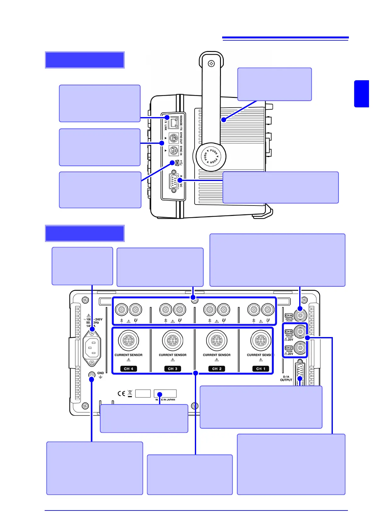
Right side
Ethernet interface jack
For LAN connection with an
Ethernet cable.
See (p. 144)
Sync interface
For synchronizing cables, as
needed.
See (p. 129)
Vent
Keep clear of obstructions.
See (p. 5)
RS-232C interface
For RS-232C cable connection, as needed.
See (p. 123), (p. 127)
USB port
For the supplied USB cable,
as needed.
See (p. 148)
Rear
Voltage input terminals
Connect Hioki-specified voltage
measurement cables.
See (p. 28)
Current input terminals
Connect an Hioki-specified cur-
rent sensor.
See (p. 28)
Power inlet
Connect the supplied
power cord.
See (p. 27)
Output terminal
Connect the supplied D-sub plug (only when
using the 9792 D/A Output option or the 9793
Motor Evaluation and D/A Output option).
See (p. 132)
CH A torque signal input BNC jack
Connect the Hioki L9217 BNC connection cable to
this terminal (only when using the 9791 Motor Eval-
uation option or the 9793 Motor Evaluation and D/A
Output option).
See (p. 138)
CH B and CH Z rotation signal
input BNC jacks
Connect the Hioki L9217 BNC connection
cable to these terminals (only when using
the 9791 Motor Evaluation option or the
9793 Motor Evaluation and D/A output option).
See (p. 138)
Serial No.
This is the instrument’s serial
number.
Functional ground terminal
Connect this terminal to a clean
common ground to suppress elec-
trical noise when measuring in an
electrically noisy environment.
See (p. 27)