4.7 Viewing Efficiency and Loss Measurement Values
80
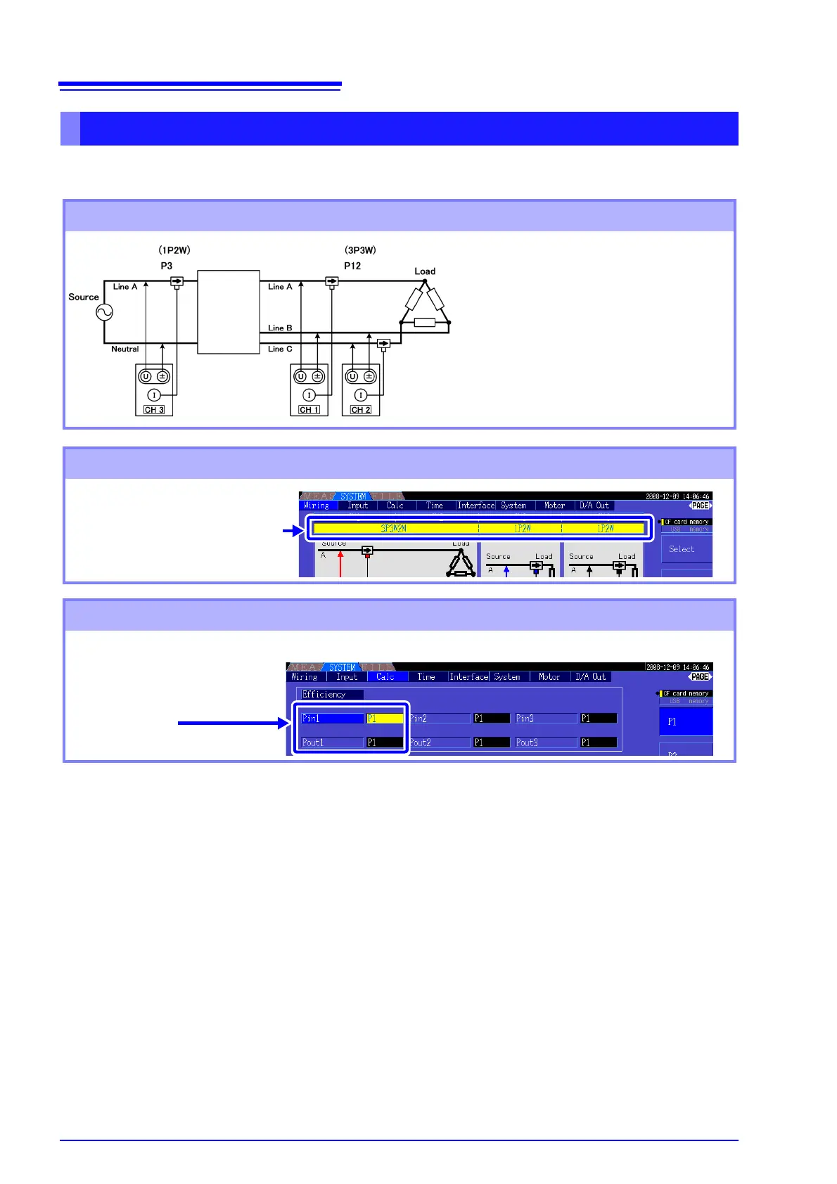
Example. Inverter input is connected to CH 3, and the outputs are connected to CH 1 and CH 2 of the
instrument.
Measuring Efficiency and Loss of an Inverter
Connection Example
Required items:
• L9438-50 Voltage Cord(2)
• 9272-10 Clamp On Sensor(1).......input side
• 9278 Clamp On Sensor (2)...........output side
input side
output side
Inverter
Wiring Mode Setting
Calculation Formula Setting
Wiring Mode 3
[3P3W2M] + [1P2W] × 2 systems
Set Pin1 to P3,
and Pout1 to P12
Calculation Formula
η1 = 100 × |P12|/|P3|
Loss1 = |P3| - |P12|