4.7 Viewing Efficiency and Loss Measurement Values
81
4
Chapter 4 Viewing Measurement Values
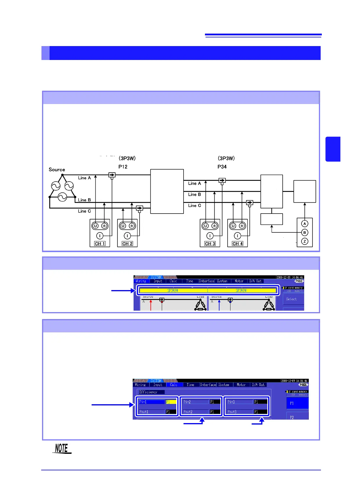
Example. Inverter inputs are connected to CH 1 and CH 2, inverter outputs to CH 3 and CH 4 of the
instrument, analog output from the tachometer to rotation signal input CH B, and analog output from the
torque meter to torque signal input CH A.
See How to connect torque meter or tachometer: 8.5 ( p.138)
Measuring Efficiency and Loss of an Inverter and Motor
Connection Example
Wiring Mode Setting
Calculation Formula Setting
Required items:(Requires Model 9791 Motor Testing Option or 9793 Motor Testing & D/A Output Option)
• L9438-50 Voltage Cord(4)
• 9272-10 Clamp On Sensor(2)........input side
• 9709 AC/DC Current Sensor (2)....output side
• Tachometer(1)......With pulse output capability
• Torque Meter(1)
• L9217 Connection Cord(2)
input side
output side
Inverter
Motor
Tachometer
Torque
Meter
Model 9791 or 9793
Wiring Mode 6
[3P3W2M] × 2 systems
Set Pin1 to P12,
and Pout1 to P34
Calculation Formula
Inverter η1 = 100 × |P34|/|P12|, Loss1 = |P12| - |P34|
Motor η2 = 100 × |Pm|/|P34|, Loss2 = |P34| - |Pm|
Total η3 = 100 × |Pm|/|P12|, Loss3 = |P12| - |Pm|
Set Pin2 to P34,
and Pout2 to Pm
Set Pin3 to P12,
and Pout3 to Pm
The torque meter and tachometer should have the fastest possible output response time.