4.8 Viewing Motor Measurement Values (With Hioki 9791 or 9793 installed)
85
4
Chapter 4 Viewing Measurement Values
To calculate motor slip, select a reference source for measuring the motor input frequency.
See "4.2.4 Frequency Measurement Settings" (p. 49)
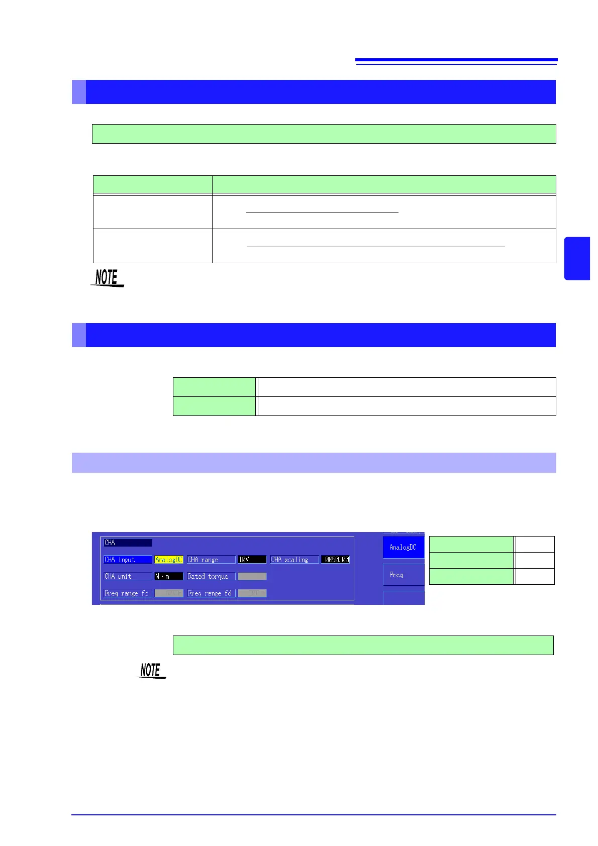
Select the type of input signal from the torque sensor connected to CH A.
CHA input
Available setting items depend on the state of the following settings.
When [CHA input] is set to [AnalogDC], set these three items to suit the sensor: [CHA range], [CHA scal-
ing], and [CHA unit].
Example. When the rated torque is 500N
• m and the torque sensor’s output range is ±10 V.
Selecting the Input Frequency Reference Source
f1, f2, f3, f4
Slip Calculation Formula
CH B Measurement Units Calculation Formula
When [Hz]
100 ×
When [r/min]
100 ×
Input Frequency - CH B Display Value
Input Frequency
2 × 60 × Input Frequency - CH B Display Value× Set No. of Poles
2 × 60 ×Input Frequency
Setting Torque Input (CH A)
• To calculate slip, set CH B to suit the rotation input signal.
• As the input frequency, select the most stable signal from the voltage and current supplied to
the motor.
AnalogDC When the sensor outputs a DC voltage proportional to the torque
Freq When the sensor outputs a frequency proportional to the torque
When [AnalogDC] is selected
CHA range 10 V
CHA scaling 50
CHA unit N•m
CHA range Select to suit the output voltage of the torque sensor.
1 V Range, 5 V Range, 10 V Range,
The CH A range can be selected with the voltage range keys from the Motor page of
the Measurement screen.