CONFIGURATION
Part. No. 2400M2501_6 Touchpoint Pro
70 Technical Handbook
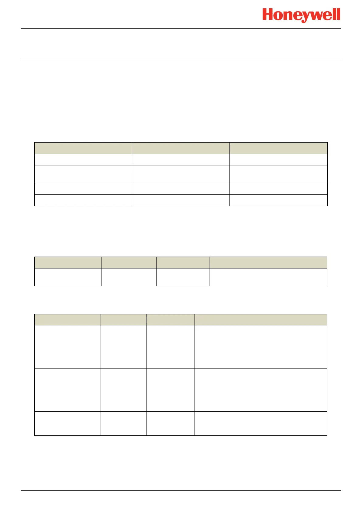
9.2.14 Rate Alarm Settings 1
The Rate of Change Alarm is triggered when a specific rate of rise or fall is observed (the Rate Alarm Trigger can be set
as Rising or Falling).
The Alarm Level and the Alarm Interval can be configured. E.g. If the Alarm Level = 10 %LEL and the Alarm Interval = 5
s, the Rate Alarm triggers if the concentration has risen by 10 %LEL within 5 s.
The rate alarm is calculated from the displayed reading.
Note: If zero suppression is used it has the effect of sensitizing the rate alarm. It is recommended to set the rate alarm to
twice the suppression band value to avoid nuisance alarms.
Access Level: Engineer
0.05*(Gas Range Max - Gas Range
Min)
Gas Range Min to Gas Range Max
Note: Rate Alarms should always be set to Latching or connected to a latching input on other equipment. A non-latching
alarm will only be displayed whilst the rate is exceeded. The alarm will reset when the gas concentration achieves full scale
or the gas rate falls below the set rate.
9.2.15 Rate Alarm Settings 2
Access Level: Engineer
Determines the Rate Alarm evaluation
interval.
9.2.16 Inhibit Delay Settings
Access Level: Engineer
If enabled, the channel will be inhibited for a specific
time interval (the Inhibit Delay Time) after power-up
in order to prevent false alarms (e.g. during sensor
warm-up).
If disabled, the channel is inhibited for a fixed 5
second delay.
Fault Recovery Delay
Enable
If enabled, the channel will be inhibited for a specific
time interval (the Inhibit Delay Time) after a channel
fault condition has been cleared in order to prevent
false alarms (e.g. due to sensor recovery).
If disabled, the channel is inhibited for a fixed 5
second delay.
This is the delay time before a channel returns to
normal operation if the Power-On Delay or the Fault
Recovery Delay is enabled.
 Loading...


