Config type
Specify the role of the port or ports in the isolation group:
• Isolated port—Assigns the port or ports to the isolation group as an isolated port
or ports.
• Uplink port—Assigns the port to the isolation group as the uplink port. This
option is not available for the switch series.
Select port(s)
Select the ports you want to assign to the isolation group.
You can click ports on the chassis front panel for selection. If aggregate interfaces
are configured, they will appear under the chassis panel for selection.
Port isolation configuration example
Network requirements
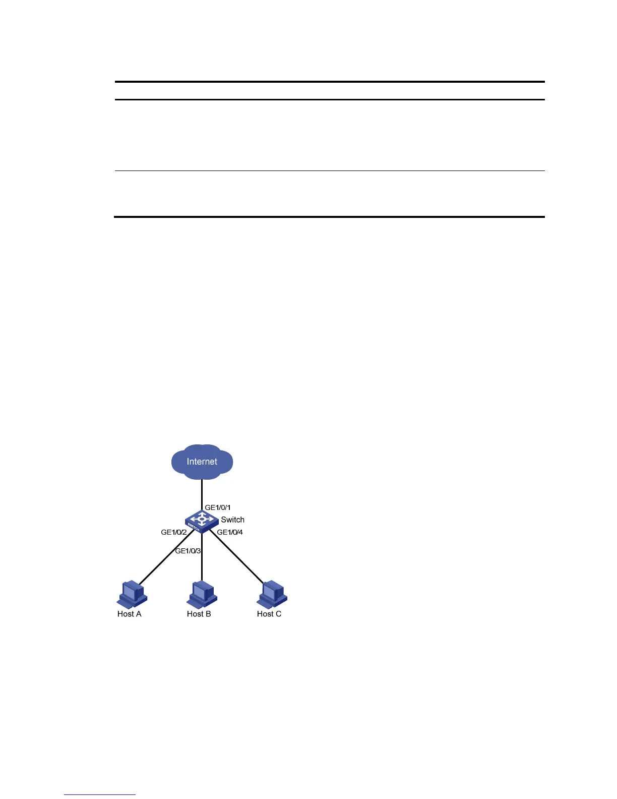
As shown in Figure 459:
• Campus network users Host A, Host B, and Host C are connected to GigabitEthernet 1/0/2,
GigabitEthernet 1/0/3, and GigabitEthernet 1/0/4 of Switch.
• Switch is connected to the external network through GigabitEthernet 1/0/1.
• GigabitEthernet 1/0/1, GigabitEthernet 1/0/2, GigabitEthernet 1/0/3, and GigabitEthernet
1/0/4 belong to the same VLAN.
Configure Host A, Host B, and Host C to access the external network but to be isolated from one another
on Layer 2.
Figure 459 Networking diagram
Configuring the switch
1. Assign GigabitEthernet 1/0/2, GigabitEthernet 1/0/3, and GigabitEthernet 1/0/4 to the
isolation group:
a. Select Security > Port Isolate Group from the navigation tree.
b. Click the Port Setup tab to enter the page shown in Figure 460.
c. Selec
t Isolated port for Config Type.