173
VPNv4 route backup for a VPNv4 route
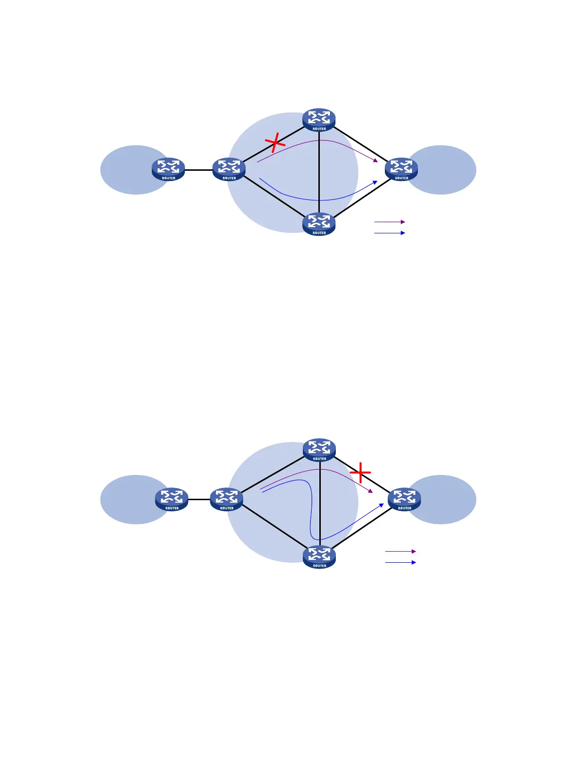
Figure 59 Network diagram
As show in Figure 59, configure FRR on the ingress node PE 1, and specify the backup next hop for
VPN 1 as PE 3. When PE 1 receives a VPNv4 route to CE 2 from both PE 2 and PE 3, it uses the
route from PE 2 as the primary link, and the route from PE 3 as the backup link.
Configure BFD for LSPs or MPLS TE tunnels on PE 1 to detect the connectivity of the public tunnel
from PE 1 to PE 2. When the tunnel PE 1—PE 2 operates correctly, traffic from CE 1 to CE 2 goes
through the path CE 1—PE 1—PE 2—CE 2. When the tunnel fails, the traffic goes through the path
CE 1—PE 1—PE 3—CE 2.
In this scenario, PE 1 is responsible for primary link detection and traffic switchover.
For more information about BFD for LSPs or MPLS TE tunnels, see "Configuring MPLS OAM."
VPNv4 route backup for an IPv4 route
Figure 60 Network diagram
As shown in Figure 60, configure FRR on the egress node PE 2, and specify the backup next hop for
VPN 1 as PE 3. When PE 2 receives an IPv4 route from CE 2 and a VPNv4 route from PE 3 (both
routes are destined for VPN 1 connected to CE 2), PE 2 uses the IPv4 route as the primary link, and
the VPNv4 route as the backup link.
PE 2 uses echo-mode BFD to detect the connectivity of the link from PE 2 to CE 2. When the link
operates correctly, traffic from CE 1 to CE 2 goes through the path CE 1—PE 1—PE 2—CE 2. When
the link fails, PE 2 switches traffic to the link PE 2—PE 3—CE 2, and traffic from CE 1 to CE 2 goes
through the path CE 1—PE 1—PE 2—PE 3—CE 2. This avoids traffic interruption before route
convergence completes (switching to the link CE 1—PE 1—PE 3—CE 2).
In this scenario, PE 2 is responsible for primary link detection and traffic switchover.
CE 2
CE
1
VPN 1
VPN
1
MPLS
backbone
PE
2
PE
1
PE
3
Primary link
Backup link
CE 2CE 1
VPN 1
VPN 1
MPLS
backbone
PE 2
PE 1
PE 3
Primary link
Backup link

 Loading...


