197
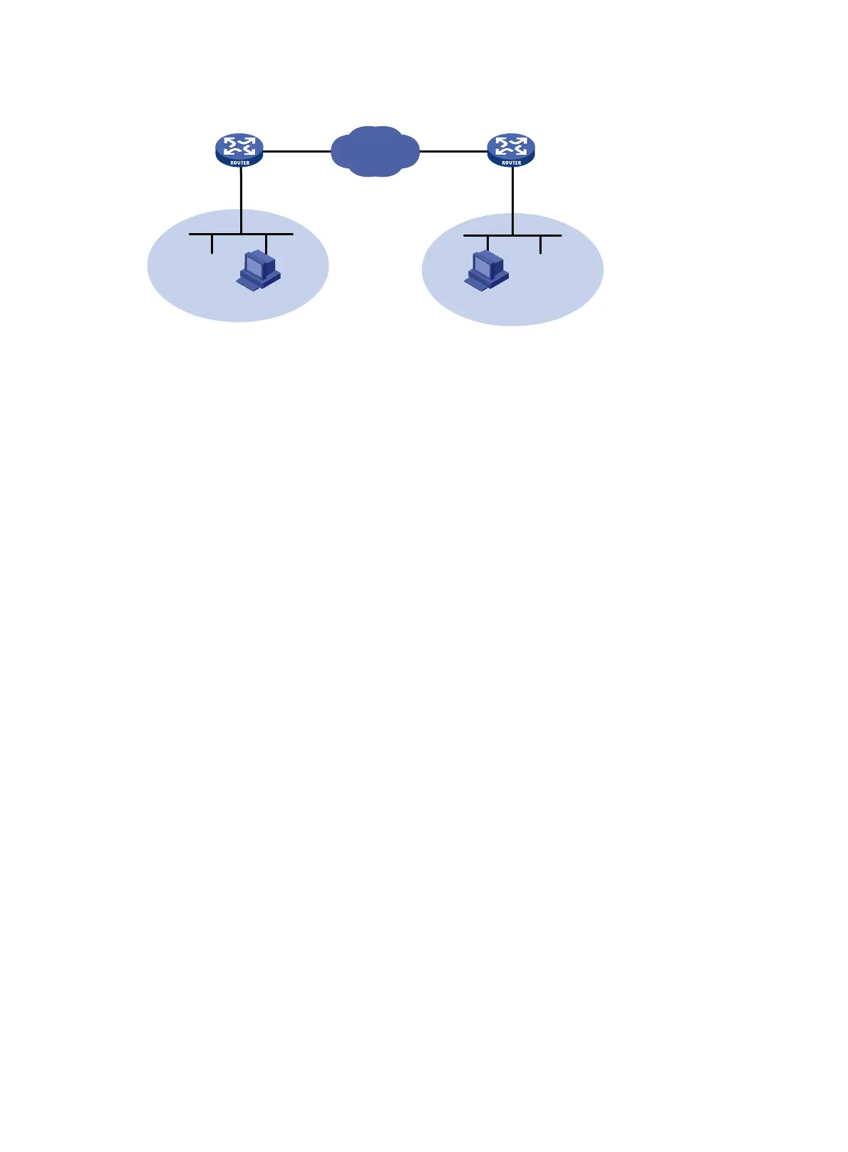
Figure 63 Network diagram
Configuration procedure
1. Assign IPv4 addresses to the interfaces on the routers according to Figure 63. Make sure
Router A and Router B can reach each other. (Details not shown.)
2. Configure Router A:
# Configure ACL 3101 to identify traffic from subnet 10.4.4.0/24 to subnet 10.5.5.0/24.
<RouterA> system-view
[RouterA] acl number 3101
[RouterA-acl-adv-3101] rule permit ip source 10.4.4.0 0.0.0.255 destination 10.5.5
0 0.0.0.255
[RouterA-acl-adv-3101] quit
# Create IPsec transform set tran1.
[RouterA] ipsec transform-set tran1
# Set the packet encapsulation mode to tunnel.
[RouterA-ipsec-transform-set-tran1] encapsulation-mode tunnel
# Use ESP as the security protocol.
[RouterA-ipsec-transform-set-tran1] transform esp
# Use DES as the encryption algorithm and SHA1-HMAC-96 as the authentication algorithm.
[RouterA-ipsec-transform-set-tran1] esp encryption-algorithm des
[RouterA-ipsec-transform-set-tran1] esp authentication-algorithm sha1
[RouterA-ipsec-transform-set-tran1] quit
# Create IKE peer peer.
[RouterA] ike peer peer
# Set the pre-shared key.
[RouterA-ike-peer-peer] pre-shared-key abcde
# Specify the IP address of the peer security gateway.
[RouterA-ike-peer-peer] remote-address 2.2.2.2
[RouterA-ike-peer-peer] quit
# Create an IPsec policy that uses IKE.
[RouterA] ipsec policy map1 10 isakmp
# Reference IPsec transform set tran1.
[RouterA-ipsec-policy-isakmp-map1-10] transform-set tran1
# Reference ACL 3101 to identify the protected traffic.
[RouterA-ipsec-policy-isakmp-map1-10] security acl 3101
# Reference IKE peer peer.
Headquarters
Branch
Internet
Router A Router B
Eth1/1
1.1.1.1/16
Eth1/1
2.2.2.2/16
Eth1/2
10.4.4.1/24
Eth1/2
10.5.5.1/24
Host A
10.4.4.4/24
Host B
10.5.5.5/24

 Loading...


