EDGE Pro Ti CNC Instruction Manual 807660 139
Maintenance and Diagnostics
4-axis DC servo board (141281)
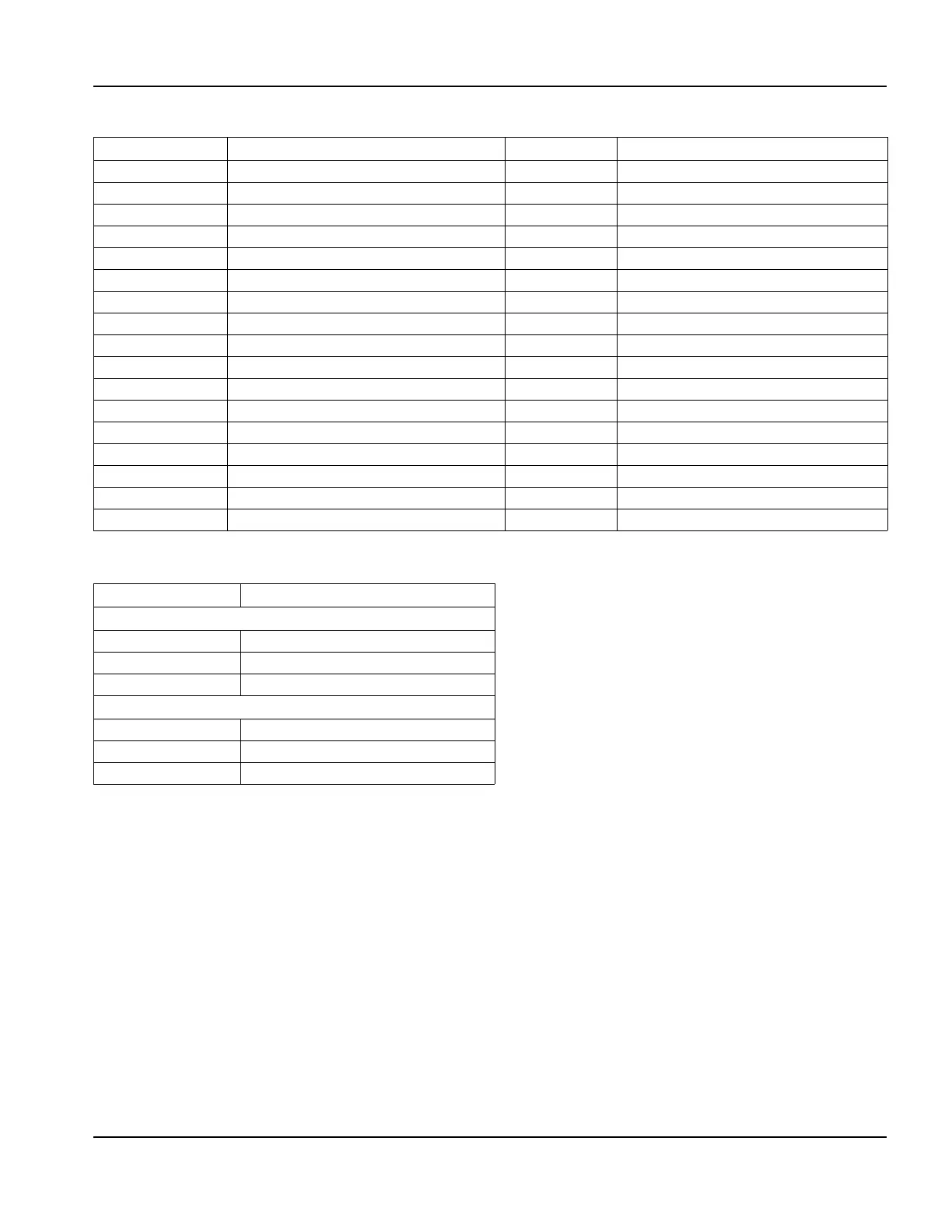
Table 41 Pinouts for J6 to I/O board (clean and field power)
Table 42 Pinouts for J7 and J8
Pin Signal Pin Signal
1 +12 V 18 Field ground
2 Field ground 19 Not connected
3 -12 V 20 Field ground
4 Field ground 21 Not connected
5 +5 V 22 Not connected
6 Field ground 23 Not connected
7 +24 V 24 Not connected
8 Field ground 25 Not connected
9 +24 V 26 Not connected
10 Field ground 27 +5 V
11 Axis 1 fault 28 Logic ground
12 Field ground 29 Logic +12 V
13 Axis 2 fault 30 Logic ground
14 Field ground 31 Logic -12 V
15 Axis 3 fault 32 Logic ground
16 Field ground 33 Logic +5 V
17 Axis 4 fault 34 Logic ground
Pin no. Signal
J7 Field 24 V output
1+24 V
2 Field ground
3 Not connected
J8 Exterior fan
1 Field ground
2+12 V
3 Field ground