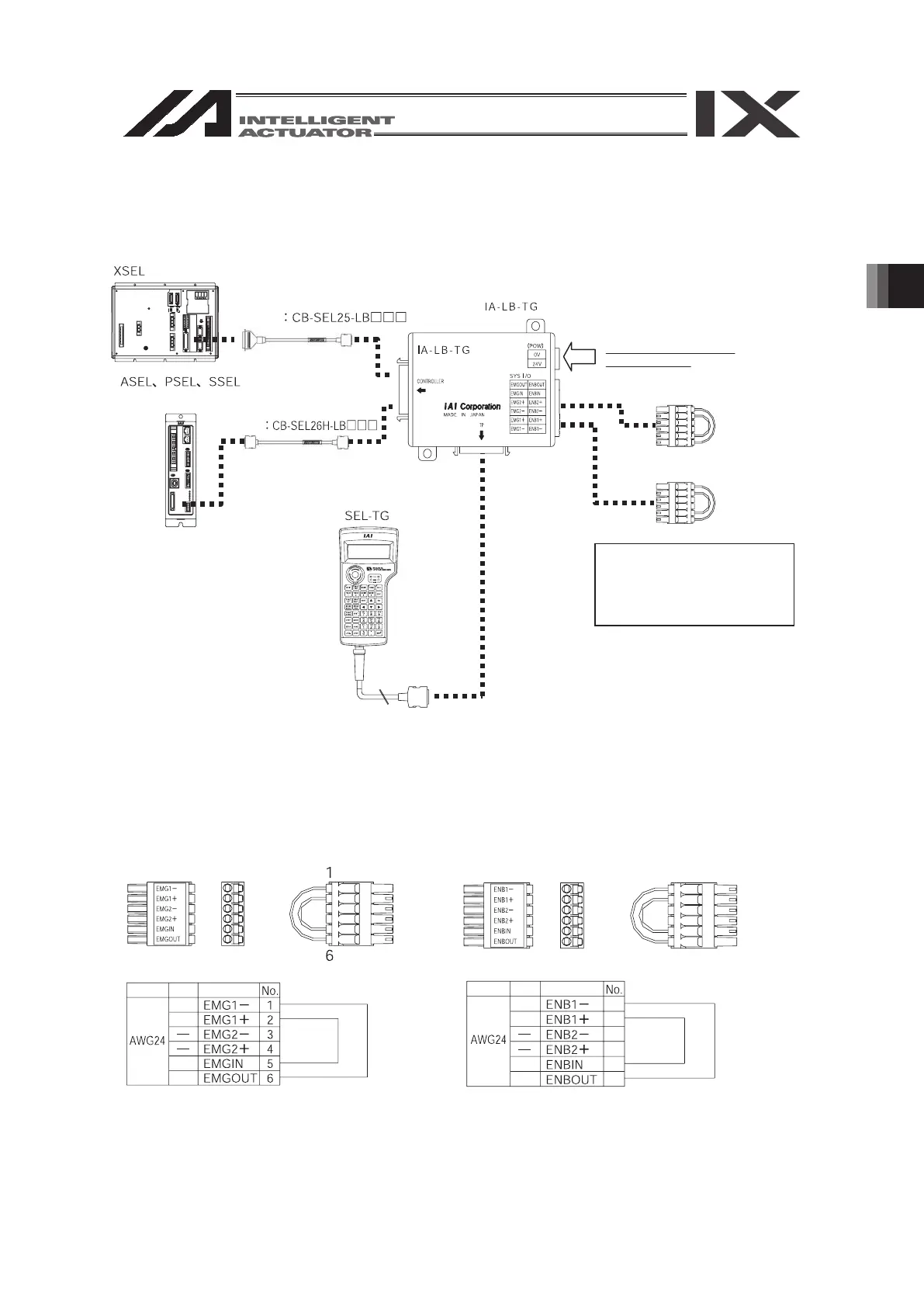
connect it to the controller as shown in the following diagram.
Controller
Controller
Model
Model
Teaching Pendant
Wiring
Color Signal
YW
YW
YW
YW
Wiring
Color Signal
YW
YW
YW
YW
Controller Adaptor Connection Cable
Controller Adaptor Connection Cable
This shows an example of
the ASE Controller.
Adaptor for the Teaching Pendant
Connector on the
ENB side
Insert the connector
with the wire arrangement
that has been kept from
the delivery time.
Connector on the
EMG side
Wire Arrangement of the Connector on the
EMG side at the time of delivery
Wire Arrangement of the Connector on the
ENB side at the time of delivery
Only when the XSEL-J controller
for connecting to DC +24 V power
source is connected, connect it to
the DC +24V power source.
Otherwise, do not connect
it to the DC +24V.
7
12
7
8
9
10
11
12
 Loading...


