7
2
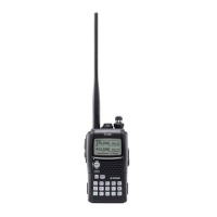
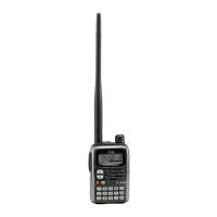
PANEL DESCRIPTION
New2001
2
• While operating in DV mode;
➥ “ DSQL” appears while the digital call sign squelch func-
tion is in use. (p. 124)
➥ “ CSQL” appears while the digital code squelch function
is in use. (p. 124)
➥ “ S” appears with the “DSQL” or “CSQL” indicator
while the pocket beep function
(with digital call sign or
digital code squelch)
is in use. (p. 125)
t KEY LOCK INDICATOR (pgs. 25, 127)
Appears when the key lock function is activated.
y AUTO POWER OFF INDICATOR (p. 96)
Appears when the auto power OFF function is in use.
u EMR/BK MODE INDICATOR (pgs. 51, 56, 107)
➥ Appears “EMR” when the EMR mode operation is se-
lected. (p. 56, 107)
➥ Appears “BK” when the break-in communication is se-
lected. (pgs. 51, 107)
i FREQUENCY READOUT
Displays a variety of information, such as operating fre-
quency, set mode contents, memory names.
• The decimal point blinks during scan.
o SKIP INDICATOR (pgs. 87, 88)
➥ “ SKIP” appears when the selected memory channel is
set as a skip channel.
➥ “ PSKIP” appears when the displayed frequency is set
as a skip frequency.
!0 MEMORY CHANNEL NUMBER INDICATOR
➥ Shows the selected memory channel number.
(pgs. 72, 73)
➥ “C” appears when the call channel is selected.
(pgs. 16, 73)
➥ “TV” appears when the TV channel is selected.
(pgs. 16, 28)
!1 S/RF METER
➥ Shows the relative signal strength while receiving sig-
nals.
➥ Shows the output power level while transmitting. (p. 24)
!2 ATTENUATOR INDICATOR (p. 22)
Appears when the RF attenuator is in use.
!3 POWER INDICATOR (p. 24)
➥ “ LOW” appears when low power is selected.
➥ “ SLO” appears when S-low power is selected.
➥ “ MID” appears when middle power is selected.
➥ No indicator appears when high power is selected.
!4 MEMORY INDICATOR (p. 72)
Appears when memory mode is selected.
!5 NAME INDICATOR (p. 78)
During memory mode operation, the programmed mem-
ory or memory bank name is displayed.
!6 MAIN BAND INDICATOR (p. 14)
Shows which operating band, “A” or “B,” is selected for the
main band.
!7 OPERATING MODE INDICATOR (p. 21)
Shows the selected operating mode.
• DV, FM, FM-N, WFM and AM are available, depending on oper-
ating band.