PLDC01938
REVISION 00
01/06/2011
TECHNICAL DEPT
Stavale
- date 05/09/2011
138/195
8
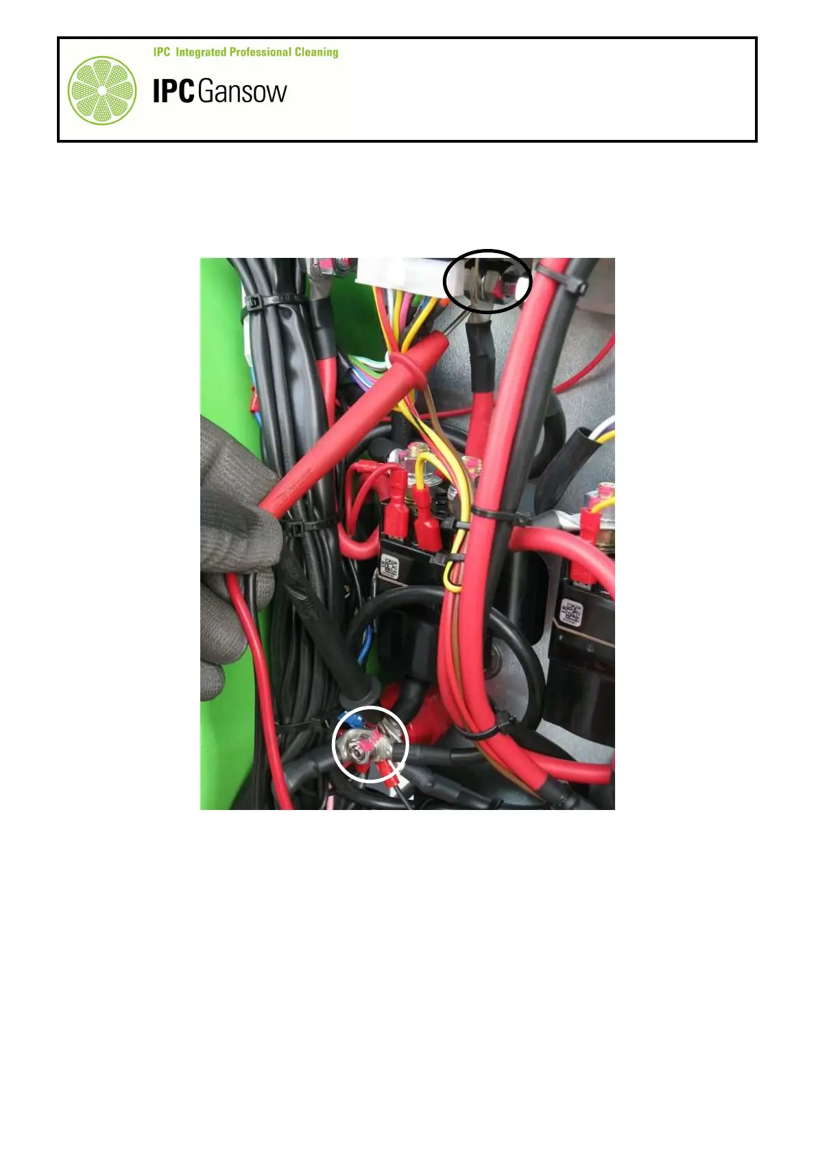
Start the machine by turning the ignition key to position “1”, wait for the drive circuit board check and verify
the input voltage on the contact B+ of the drive board C.
9
Then move the probe from the power contact B1 to the board contact B+ (keeping the black probe on the
negative insulator) and read the input voltage V3.
10
The voltages V1 - V2 - V3 must all be equal or slightly lower, otherwise:
10a
If the voltages V1 - V2 - V3 are very different, check the wiring and/or the power contacts B1 - B2 of the
contactor B and verify the state of the main fuse F1.
10b
If there is no voltage in V3, check for possible alarms and/or verify the efficiency of the contacts of the
contactor B by means of the status LED on the control panel or the circuit board itself.
10c
Proceed to check the signals to the drive circuit board by means of the logic connector, see following
paragraph.
10d
If the voltages V1 - V2 - V3 are equal, then proceed to verify the current draw of the drive motor.
V3
B+
B
PHOTO 294
A