PLDC01938
REVISION 00
01/06/2011
TECHNICAL DEPT.
Stavale
- date 05/09/2011
35/195
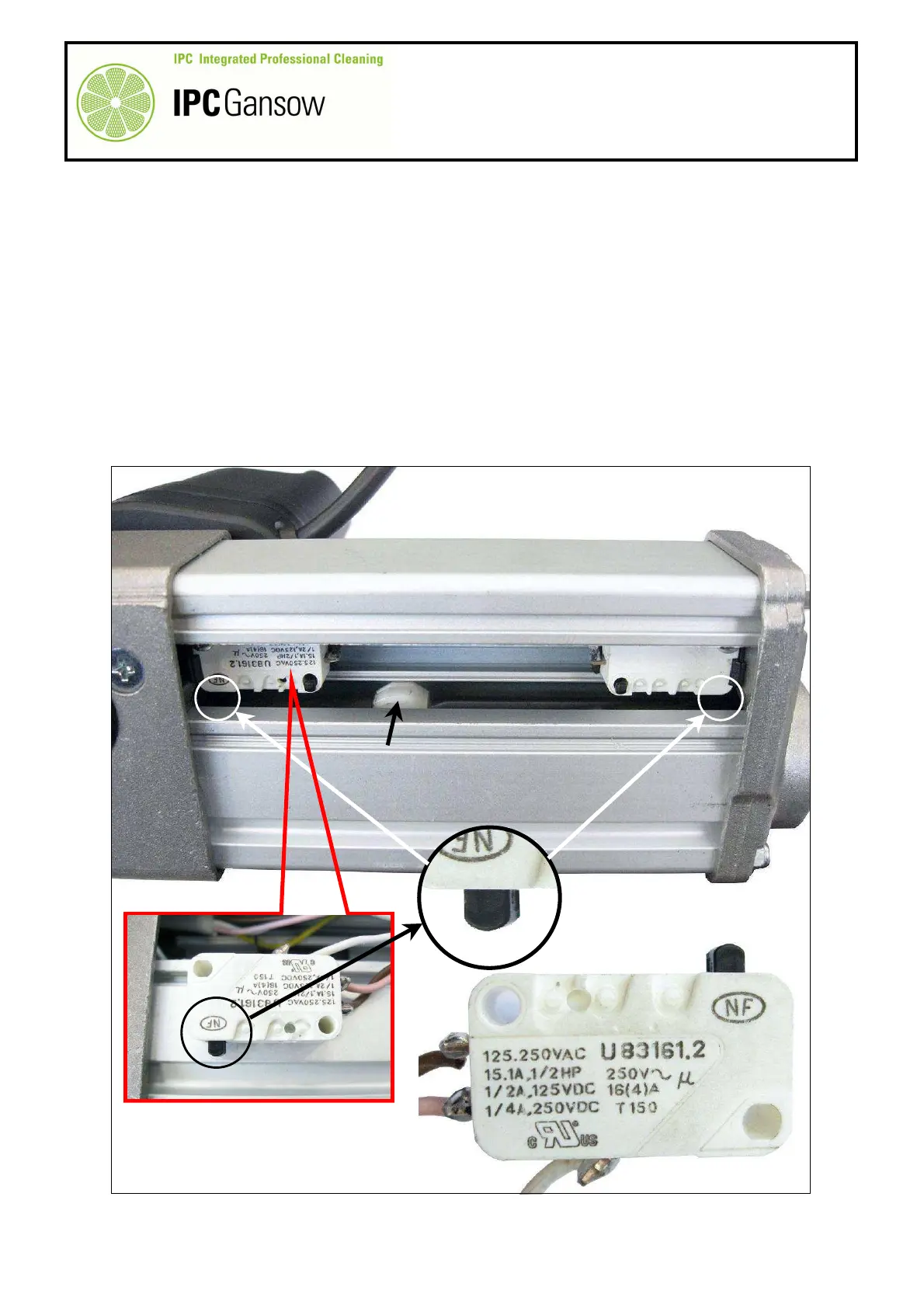
A2.4 Checking head actuator operation manually on the bench
Description
There are two micro switches in the body of the actuator, one, X, is positioned at the bottom on
the side of the motor Z, the other, Y, is positioned at the top on the rod side W. They signal the
limits (bottom and top respectively) of rod travel to the circuit board controlling raising and
lowering. In addition, in the case of the actuator in question (head pressure and raising),
reaching the top micro switch not only notifies the control panel board that the end of travel has
been reached, but also, through the control panel display, warns when the brushes are worn
and need changing.
The linear travel of the cam K on the rod actuates one of the two micro switches (bottom X or
top Y). When one of the micro switches is tripped, it makes a mechanical noise (a sort of click)
which indicates it has been actuated.
K
W
X / Y
PHOTO 76
i
i