PLDC01938
REVISION 00
01/06/2011
TECHNICAL DEPT
Stavale
- date 05/09/2011
139/195
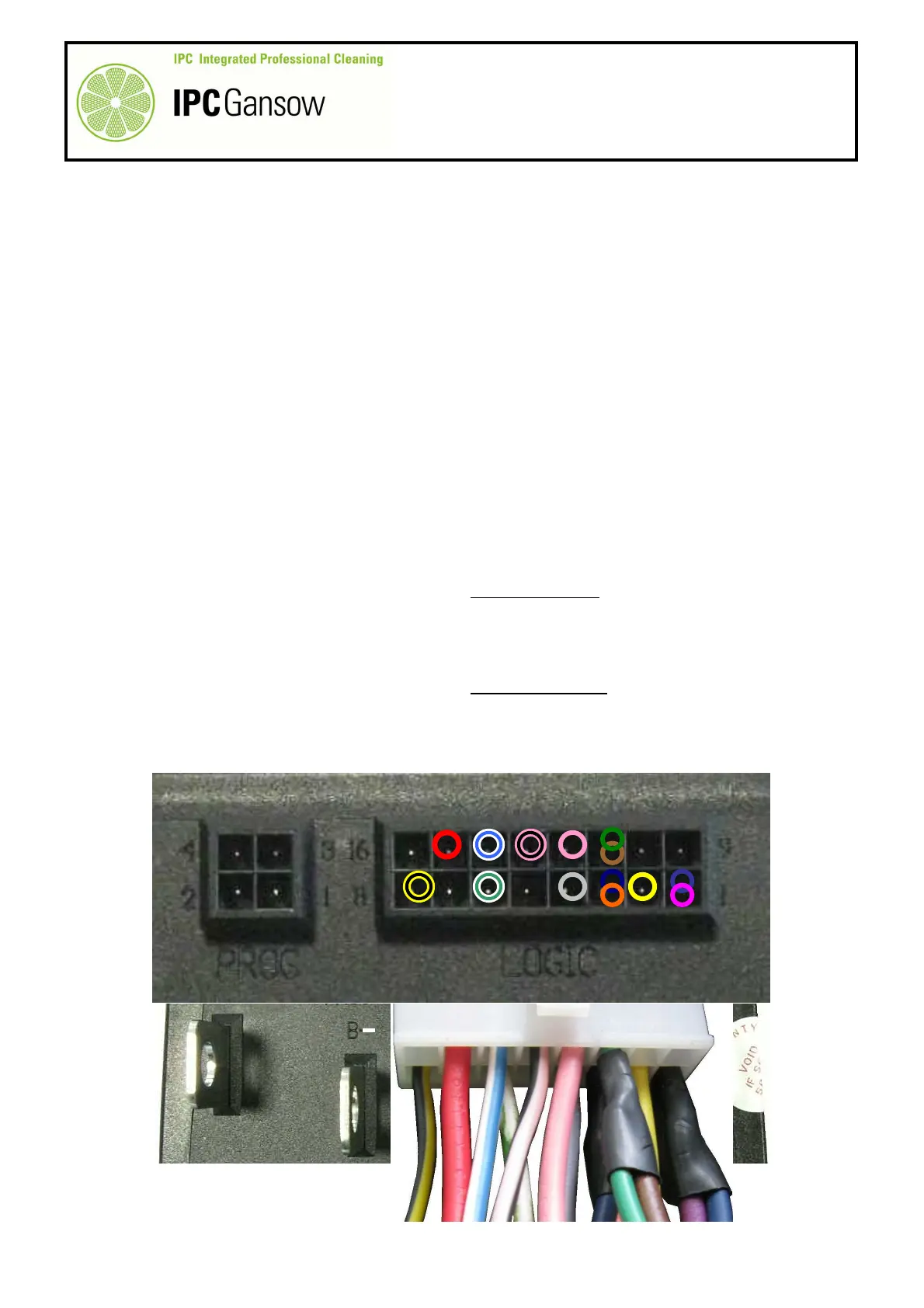
C1.2 Checking the input signals on the drive logic board
The drive circuit board communicates with the rest of the machine electronics through the 16
pin connector marked “LOGIC”. The wires carrying both passive signals (they receive the
signal) and active signals (they activate a command by means of a signal) are connected to
this connector. The absence of certain passive signals may trigger a board alarm, others do
not. This means that the machine does not move and no error is signalled on the drive board.
Checks
1
Make sure the batteries on the machine are charged.
2
Obtain an accurate digital multimeter (tester).
3
Move the machine onto a flat dry area of floor.
4
Turn the ignition key to position "0".
5
Remove the bumpers and the front panel.
6
Turn the ignition key to position “1” and check the inputs.
7
With the multimeter, measure the input voltage between the RED wire on pin 15 and the negative power
contact B-. If correct, the voltage should equal +36 V.
7a
If there is no voltage, check the key contact and/or the continuity of the RED wire itself.
8
Read the output voltage between the WHITE-BLUE wire, pin 14, and the negative power contact B-. The
voltage must equal +36 V. This voltage powers the LED on the control panel which displays the drive board
error codes.
9
By means of the selector on the control panel, select reverse movement and measure the input voltage
between the PINK-BLACK wire, pin 13, and the negative power contact B-. If correct, the voltage should
equal +36 V.
9a
If there is no voltage, check operation of the drive direction selector on the control panel, the presence of an
output voltage of +36 V from the wire powering the selector and the presence of continuity on all wires.
10
By means of the selector on the control panel, select forwards movement and measure the input voltage
between the PINK wire, pin 12, and the negative power contact B-. If correct, the voltage should
equal +36 V.
10a
If there is no voltage, check operation of the drive direction selector on the control panel, the presence of an
output voltage of +36 V from the wire powering the selector and the presence of continuity on all wires.
8
1
B
PHOTO 295
i