PLDC01938
REVISION 00
01/06/2011
TECHNICAL DEPT.
Stavale
- date 05/09/2011
52/195
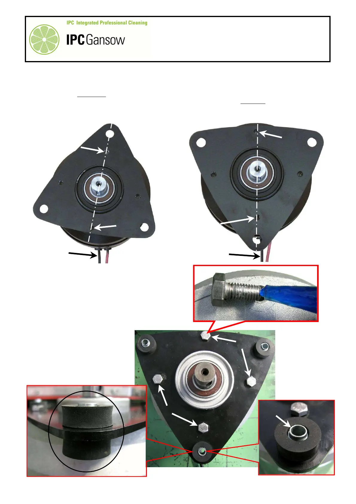
Remounting the 1050 head
9
Position the new brush motor L using the power wires L1 as a reference.
10
Place the brush motor flange H on the motor L (1050).
11
To mount the right motor, position the hole H1 on the same axis as the outlet of the brush motor power wires
L1, keeping the hole H2 on the opposite side of the wires L1. To mount the left motor, position the hole H2
on the same axis as the outlet of the brush motor power wires L1, keeping the hole H1 on the opposite side
of the wires L1.
12
Clean the screws I to remove previous thread lock.
13
Apply thread lock to the screws I to avoid them coming
unscrewed.
14
Screw up the screws I and tighten with a maximum
torque of 18.5 Nm (~ 1.8 kgm).
15
Position the vibration dampers G on the flange H,
respecting the orientation of the bushing G1.
16
Mount the flange complete with
vibration dampers on the head,
making sure the smaller diameter
of the bushing G1 enters the hole
in the head.
PHOTO 119
L1
L
H
H1
L
L1
PHOTO 118
Right
Left
PHOTO 120
I
I
I
G
G
G1
I