PLDC01938
REVISION 00
01/06/2011
TECHNICAL DEPT.
Stavale
- date 05/09/2011
38/195
15
Connect the red wire E1 to the positive pole of the battery and the black wire E2 to the negative pole (a 6 V -
24 V battery is sufficient, providing it is charged and of a good capacity).
16
If the actuator A is also operating correctly during retraction, the rod A1 will start moving, retracting inside
the body of the actuator. Let the bottom micro switch (X) in the body of the actuator A stop retraction of the
rod A1.
17
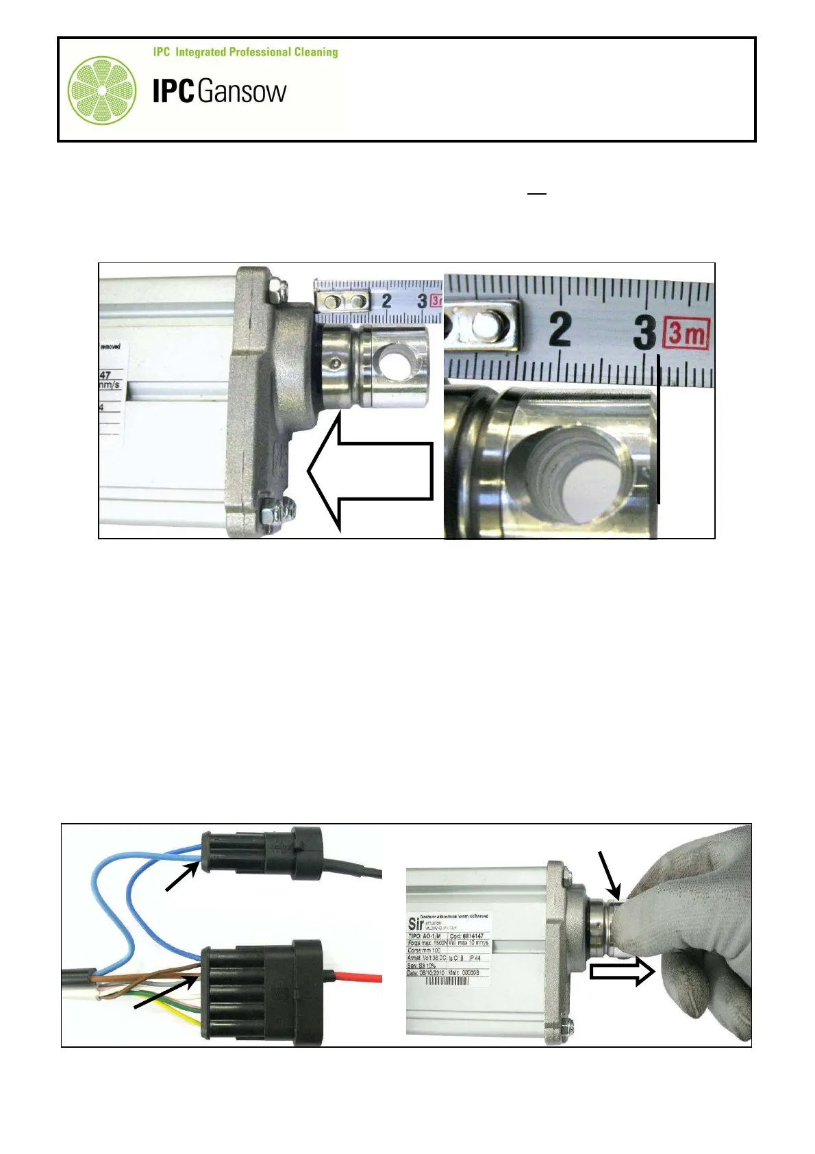
Travel of the rod A1 is always ~ 100 mm, so measuring it from the edge of the body of the actuator A should
give a maximum length of 30 mm ± 2 mm.
Result
Checking motor and internal micro switch operation
18
If the actuator is operating correctly, put it back on the machine and then test manually as described in
paragraph A2.2, controlling current draw as described in paragraph A2.1.
19
If the actuator does not move from its position, check operation of the motor and micro switches individually.
Checking operation of the motor
20
Using the two electric wires E1 - E2 used previously, check the rotation direction of the motor Z.
21
Place the actuator A with the axis of the hole in the rod A1 on the same plane as the hole in the rigid support
A2 as described previously.
22
Connect the red wire E1 to the brown wire (to the motor) by means of the connector B in the B2 position,
and the black wire E2 to the blue wire (to the motor) by means of the connector C in the C2 position.
23
Hold the rod A1 of the actuator A with one hand to prevent it from turning.
24
Connect the red wire E1 to the positive pole of the batteries and the black wire E2 to the negative pole.
A
A1
PHOTO 82
30 mm ±2 mm
30 mm ± 2 mm
Travel ~100 mm
A1
A
E1
E2
C2
B2
PHOTO 83
C
B
1 2
1 2 3 4 5