PLDC01938
REVISION 00
01/06/2011
TECHNICAL DEPT.
Stavale
- date 05/09/2011
37/195
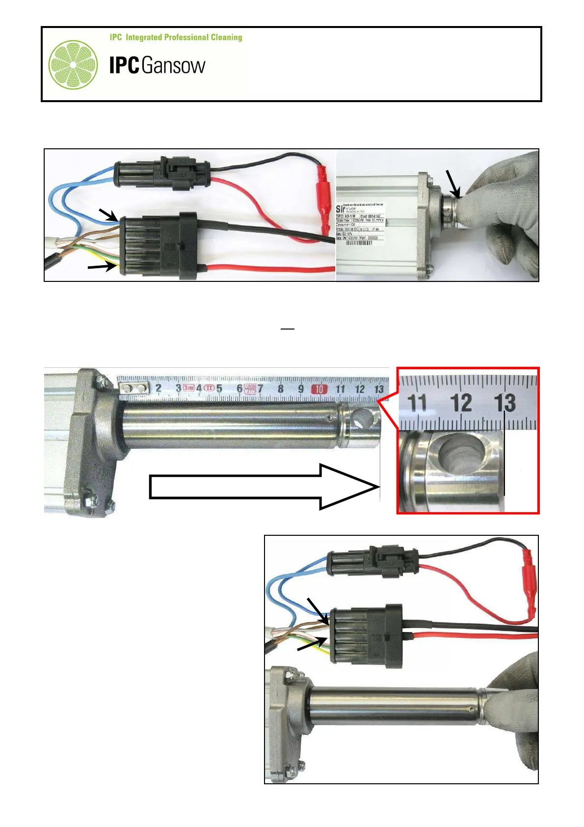
7
Connect the red wire E1 to the yellow wire B5 and the black wire E2 to the blue wire B1 of the actuator
motor.
8
Hold the rod A1 of the actuator A with one hand to prevent it from turning.
9
Connect the wire E1 to the positive pole of the battery and the wire E2 to the negative pole (a 6 V - 24 V
battery is sufficient, providing it is charged and of a good capacity).
10
If the actuator A is operating correctly the rod A1 will start moving, emerging from the body of the actuator.
Let the micro switch in the body stop the rod A1 emerging.
11
Travel of the rod A1 is ~ 100 mm, so measuring it from the edge of the body of the actuator A should give a
maximum length of 130 mm ± 2 mm.
12
Then check the opposite movement, with
the rod A1 retracting back into the body of
the actuator A. This verifies correct
operation of the electric motor Z, rod A1
and bottom micro switch (X).
13
Connect the red wire E1 to the white wire
in the B3 position and the black wire E2 to
the brown or grey wire in the B2 position.
14
Hold the rod A1 of the actuator A with one
hand to prevent it from turning.
5
4 3
1
1
2
B5
B1
E2
E1
A1
A
TRAVEL ~100 mm / LENGTH 130 ± 2 mm
A1
A
A2
PHOTO 80
B2
B3
E1
E2
A
A1
D
C
B
PHOTO 81
1 2 3 4 5