PLDC01938
REVISION 00
01/06/2011
TECHNICAL DEPT.
Stavale
- date 05/09/2011
36/195
Checks
1
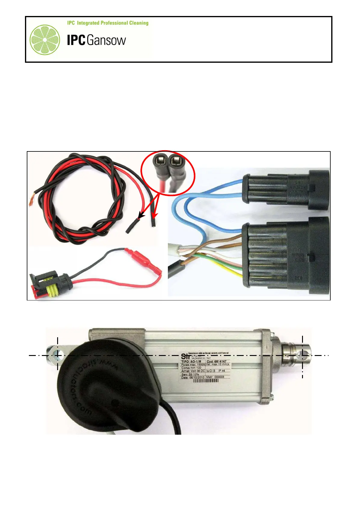
Before replacing the actuator A, check visually that there are no burnt areas on the motor and that the wires
are tightly crimped to the terminals of the connectors B and C and are not damaged. Then check operation
manually.
2
Check that the rod A1 emerges easily by unscrewing it by hand.
3
If points 1 and 2 are OK, proceed with the electrical test as described below.
4
Obtain two wires E1 - E2 with different colours (see photograph below) with plugs for insertion in the
terminals of the connector B.
5
Also obtain a bridge D for the fuse connector C and connect it.
6
Place the actuator A with the axis of the hole in the rod A1 on the same plane as the hole in the rigid support
A2.
For testing, the actuators can be powered at a voltage of less than 36 V.
A single 6 V battery is sufficient, providing it has a good amperage (A) as the low voltage (V)
must be compensated for by the amps (A).
B
C
A1
PHOTO 78
A2
Z