PLDC01938
REVISION 00
01/06/2011
TECHNICAL DEPT
Stavale
- date 05/09/2011
181/195
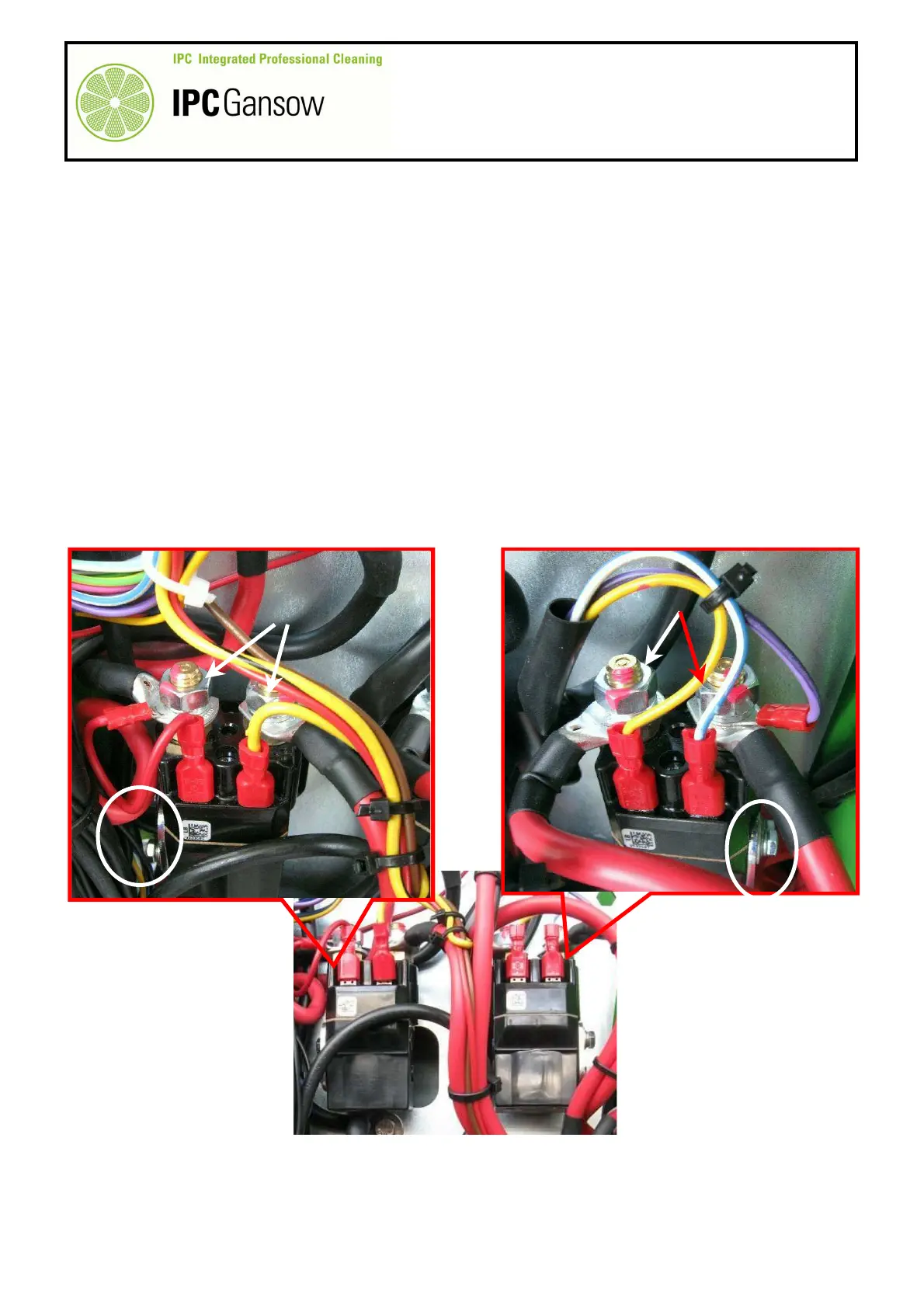
D3.1 Contactor TL1 (functions) and TL2 (drive)
1
Move the machine onto a flat dry area of floor.
2
Brake the machine by pressing the pedal to put the parking brake on.
3
Place the ignition key in the “0” position and disconnect the batteries from the main machine wiring.
4
Remove the bumpers, and front panel.
Disassembly TL1
5
On the electronics plate, identify the functions board contactor TL1.
6
Disconnect the control wires with fastons first, then the large section power wires with eye terminals fastened
with the nuts A.
7
Remove the contactor by unscrewing the two screws C at the side and replace it with a new one.
Disassembly TL2
8
On the electronics plate, identify the drive board contactor TL2.
9
Disconnect the control wires with fastons first, then the large section power wires with eye terminals fastened
with the nuts B.
10
Remove the contactor by unscrewing the two screws C at the side and replace it with a new one.
Reassembly
1
To assemble the new contactors, complete the disassembly operations in reverse.
2
Tighten the nuts on the power terminals A and B with a maximum torque of 6 N/m.
PHOTO 370
TL1
TL2
C
C
TL1
TL2
A
B