PLDC01938
REVISION 00
01/06/2011
TECHNICAL DEPT
Stavale
- date 05/09/2011
141/195
14
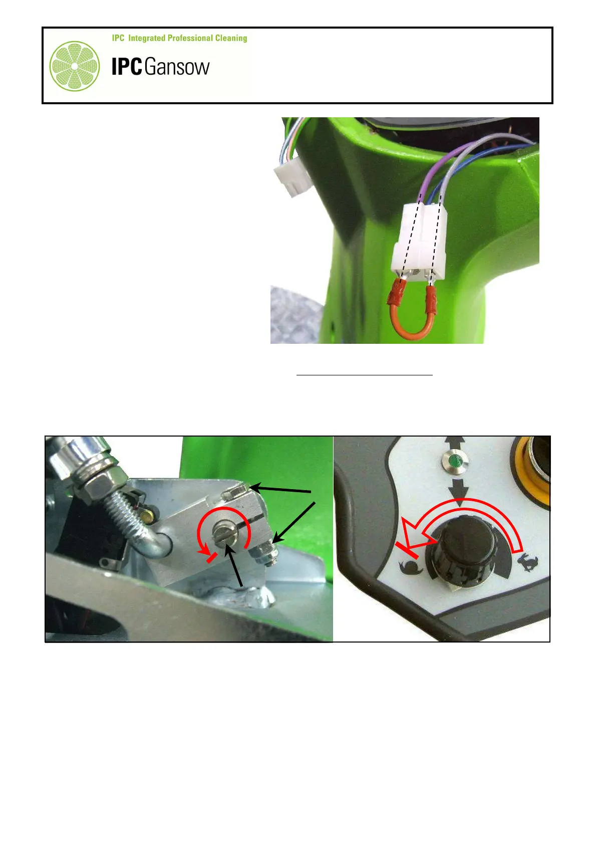
The wires used by the two potentiometers
on the control panel and on the accelerator
pedal are connected from pin 4 to pin 1.
Pin 3 and pin 1 are common to the two
potentiometers. Pin 4 is assigned to the
control panel potentiometer and pin 2 to
the accelerator pedal potentiometer.
14a
If the control panel potentiometer
malfunctions (the machine generally
moves at minimum speed even when the
control panel potentiometer is set to
maximum), the problem can be resolved by
disconnecting the potentiometer connector
C from the wiring connector D and
connecting the bridge E on the wiring
connector between the PURPLE wire, pin
1, and the GREY wire, pin 4.
14b
If the accelerator pedal potentiometer malfunctions, the only solution (to be adopted as an emergency
measure only when the machine must be moved), if allowed by the potentiometer, is to loosen the bolt F
and turn the potentiometer shaft G anticlockwise. This procedure must only be performed in combination
with the control panel potentiometer H, setting the latter to minimum speed by turning it anticlockwise and
regulating the speed with the machine moving only. To avoid drive board error, you are not recommended to
disconnect the entire accelerator pedal from the wiring by means of the relative connectors.
15
It is possible that, with no malfunction indicated on the display or by the control panel LED and with forwards
or reverse drive selected, the machine does not start to move. This may be due to malfunction of the control
panel direction selector, or to a poorly connected or detached wire. If the malfunction occurs with both
forwards and backwards movement, the problem could be with the +36 V positive red wire powering the
direction selector. If the malfunction is in one of the two directions, the problem could be caused by a poorly
connected pink wire (forwards movement) or pink-black wire (backwards movement) or, by a break in
electrical continuity between the deviator and the drive board.
PHOTO 298
H
F
C
PHOTO 297
E