4-132 4222983 Second Edition
ELECTRICAL
4
Figure 4-86
6. Measure the resistance between terminals (1 and 2).
Is the resistance value 0.02 ohms or less?
YES Switch is faulty; replace switch.
NO Proceed to step 7.
7. Depress the seat switch and measure the resistance
between terminals (1 and 2).
Is the resistance value 0.02 ohms or less?
YES Switch is good.
NO Switch is faulty; replace switch.
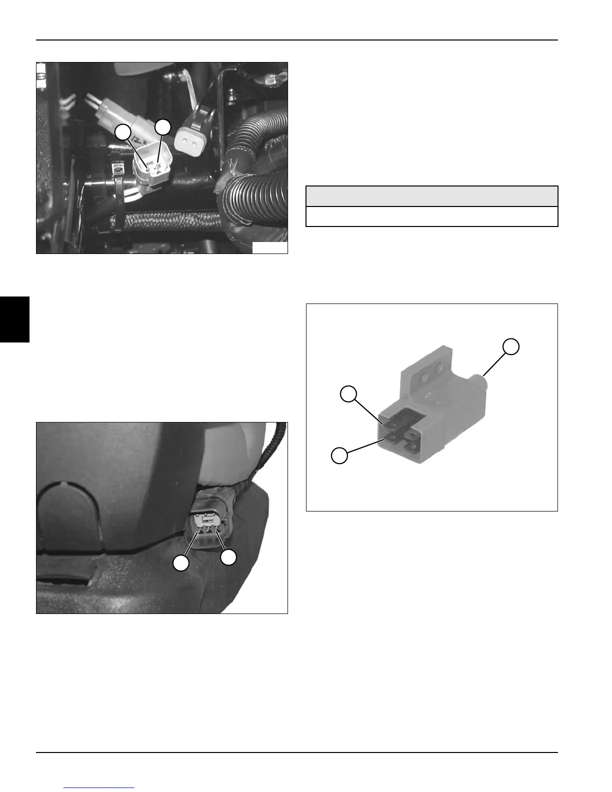
Figure 4-87
8. Measure the resistance between terminals (3 and 4).
Is the resistance value 0.02 ohms or less?
YES Switch is faulty; replace switch.
NO Proceed to step 9.
9. Depress the seat switch and measure the resistance
between terminals (3 and 4).
Is the resistance value 0.02 ohms or less?
YES Switch is good.
NO Switch is faulty; replace switch.
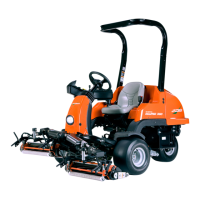
Brake Pedal Switch Test
See Figure 4-88.
1. Park the mower safely. (See “Park Mower Safely” on
page 1-6.)
2. Remove brake pedal switch. (See “Brake Pedal
Switch” on page 4-156.)
Figure 4-88
3. Set the meter to read ohms.
4. Touch meter leads to each other and confirm a
resistance value of 0.0 ohms.
5. Measure the resistance between terminals (1 and 3).
Is the resistance value 0.02 ohms or less?
YES Switch is faulty; replace switch.
NO Proceed to step 6.
6. Depress the switch button (2) and measure the
resistance between terminals (1 and 3).
Is the resistance value 0.02 ohms or less?
YES Switch is good.
NO Switch is faulty; replace switch.
1
2
TN2738
3
4
TN1887
Required Tools or Equipment
Digital Multimeter or Ohmmeter
3
2
TN2374
1