ELECTRICAL
4222983 Second Edition 4-155
4
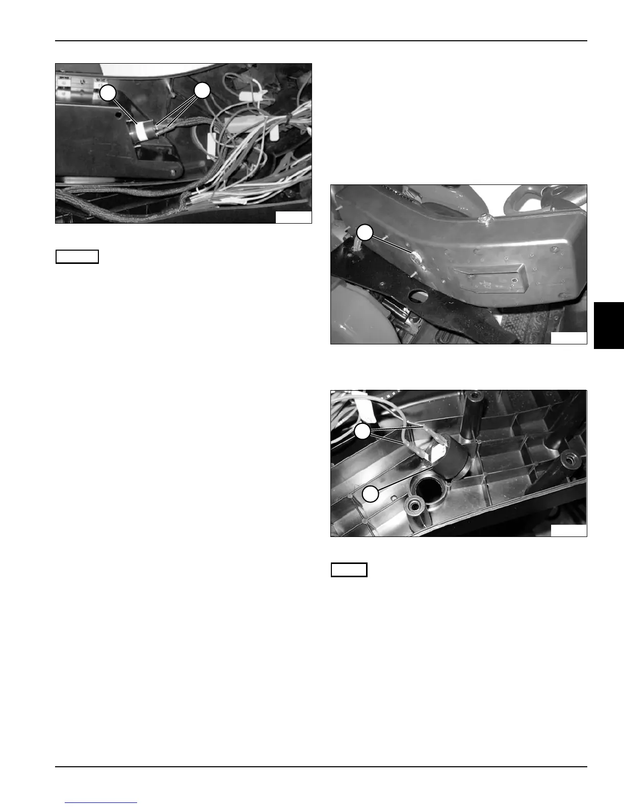
Figure 4-138
NOTES
• For installation purposes, note orientation of the 12
VDC accessory plug (2).
• Label all wires before disconnecting to ensure correct
installation.
4. Disconnect wire connectors (3).
5. Remove 12 VDC accessory plug (2).
Installation Notes
• Use new cable ties to secure wire connectors and
wire harness.
• Install the 12 VDC accessory plug by reversing the
order of removal.
• Apply dielectric grease (Jacobsen PN 365422) to any
connectors removed.
Horn
Removal and Installation
See Figures 4-139 and 4-140.
1. Park the mower safely. (See “Park Mower Safely” on
page 1-6.)
2. Remove instrument panel. (See “Instrument Panel”
on page 4-151.)
Figure 4-139
3. Remove retaining ring (1).
Figure 4-140
NOTE
Label all wires before disconnecting to ensure correct
installation.
4. Disconnect wire connectors (3).
5. Remove horn (2).
Installation Notes
• Install horn by reversing the order of removal.
• Apply dielectric grease (Jacobsen PN 365422) to any
connectors removed.
TN2336
2
3
TN2332
1
3
2
TN2351