CHASSIS
4222983 Second Edition 5-19
5
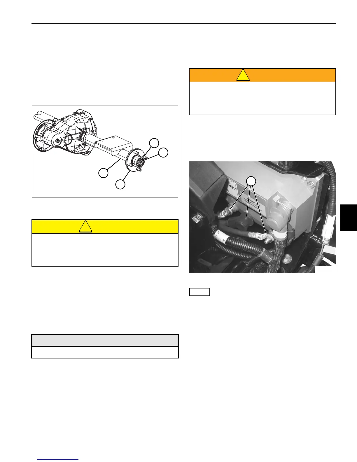
Front Wheel Hub
Removal and Installation
See Figure 5-27.
1. Park the mower safely. (See “Park Mower Safely” on
page 1-6.)
2. Remove front wheel. (See “Front Wheels” on
page 7-14.)
Figure 5-27
3. Remove cotter pin (2).
CAUTION
4. Loosen, but do not remove, castle nut (1).
5. Loosen wheel hub (3) from front axle assembly (4)
using a suitable puller.
6. Remove castle nut (1).
7. Remove wheel hub (3) from front axle assembly (4).
Installation Notes
• Apply anti-seize compound to axle shaft splines.
• Install front wheel hub by reversing the order of
removal.
• Torque castle nut (1) to 95–115 lb-ft (10.7–13.0 N·m).
Front Axle Assembly
Removal and Installation
See Figures 5-28 through 5-30.
WARNING
1. Park the mower safely. (See “Park Mower Safely” on
page 1-6.)
2. Remove axle shield and front splash shield. (See
“Axle Shield and Front Splash Shield” on page 5-17.)
Figure 5-28
NOTE
Label all wires before disconnecting to ensure correct
installation.
3. Disconnect AC traction motor power cables (1).
4. Remove cable ties securing the AC traction motor
power cables to the frame.
The wheel hub may move unexpectedly when
using a puller. To prevent injury and/or property
damage, do not remove the castle nut until the
wheel hub has been loosened from the axle.
Required Materials
Anti-Seize Compound
TN2812
TN2812
4
1
2
3
Be sure that the key switch is off, all electrical
accessories are turned off, and the 12-volt and
48-volt power connectors are disconnected
before starting work on machine.
TN2723
1