4-148 4222983 Second Edition
ELECTRICAL
4
NOTE
Label all wires before disconnecting to ensure correct
installation.
4. Disconnect wire connectors (3).
5. Firmly hold the 12A circuit breaker (4) and unscrew
the protective rubber cover (5).
6. Repeat steps 4 and 5 to remove the 30A circuit
breaker (6) and 50A circuit breaker (7).
Installation Notes
• Install circuit breakers by reversing the order of
removal.
• Apply dielectric grease (Jacobsen PN 365422) to any
connectors removed.
Contactors
Removal and Installation
See Figures 4-121 through 4-123.
WARNING
1. Park the mower safely. (See “Park Mower Safely” on
page 1-6.)
2. Remove PDU. (See “PDU” on page 4-139.)
Figure 4-121
3. Remove six screws (2).
4. Remove PDU cover (1) and PDU seal (3).
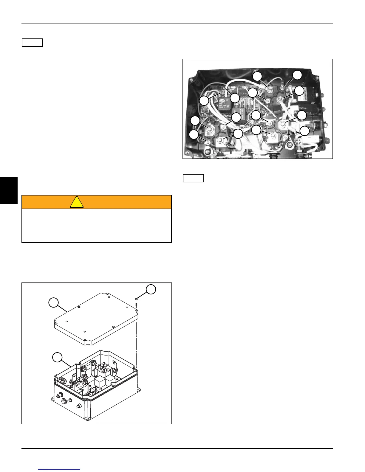
Figure 4-122
NOTE
Label all wires before disconnecting to ensure correct
installation.
5. Remove nuts (4 and 5) and disconnect wire
terminals.
6. Remove circuit board mounting screws (7).
Be sure that the key switch is off, all electrical
accessories are turned off, and the 12-volt and
48-volt power connectors are disconnected
before starting work on machine.
TN2835
TN2835
2
3
1
TN2834
5
4
5
4
5
45
4
4
5
4
5
6
7