CUTTING UNITS
4222983 Second Edition 6-27
6
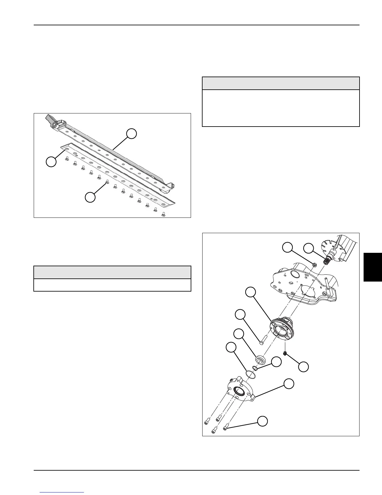
Bedknife
Removal and Installation
See Figure 6-29.
1. Park the mower safely. (See “Park Mower Safely” on
page 1-6.)
2. Remove bedknife backing assembly. (See “Bedknife
Backing Assembly” on page 6-26.)
Figure 6-29
3. Remove screws (2) and bedknife (3) from the
bedknife backing (1).
Installation Notes
• Install bedknife by reversing the order of removal.
• Apply anti-seize compound to screws (2).
• Tighten screws (2) to 90–120 lb-in. (10.2–13.6 N·m),
starting with screws in the center and working out to
the ends of the bedknife.
• Grind bedknife after assembling to bedknife backing
to achieve a 0.0625 in. (1.59 mm) bedknife front face
height, a 5° bedknife front face angle, and an 8–10°
bedknife top face angle (rear relief) [5–7° if equipped
with a Super Tournament bedknife].
• Adjust the bedknife-to-reel clearance. (See
“Bedknife-to-Reel Clearance Adjustment” on
page 6-16.)
Reel Bearing Housing Assembly
Removal and Installation—Drive Side
See Figure 6-30.
1. Park the mower safely. (See “Park Mower Safely” on
page 1-6.)
2. Remove cutting unit from the mower. (See “Center
Cutting Unit” on page 6-24 or “Right and Left Cutting
Units” on page 6-25.)
3. Remove front roller. (See “Front Roller” on
page 6-31.)
4. Remove grass shield. (See “Grass Shield” on
page 6-25.)
5. Remove reel drive motor. (See “Reel Drive Motor” on
page 6-23.)
Figure 6-30
Required Materials
Anti-Seize Compound
TN2635
1
2
3
Required Tools or Equipment
• Bearing Assembly Tool
(Jacobsen PN JAC5084)
• Reel Bearing Housing Puller
(Jacobsen PN JAC5085)
TN1698
9
8
2
7
10
6
5
4
3
1