ELECTRICAL
4222983 Second Edition 4-165
4
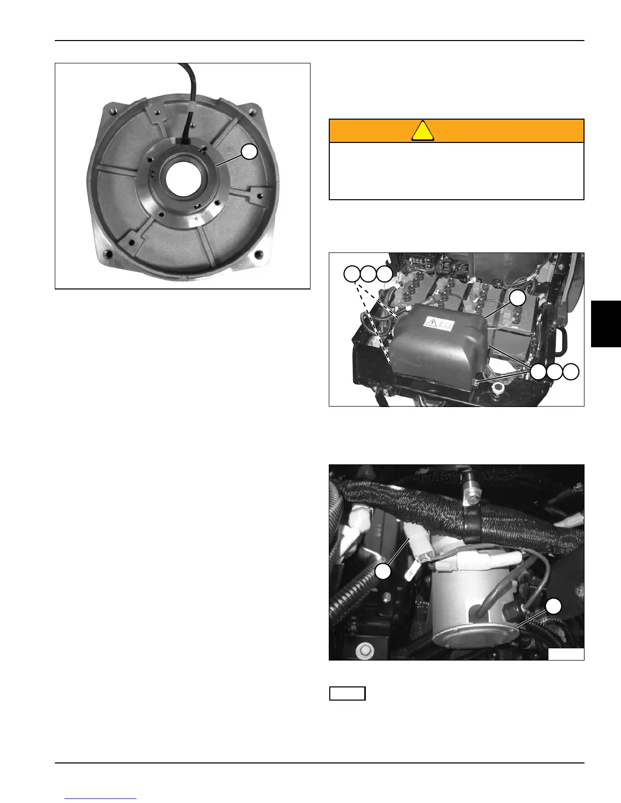
Figure 4-162
11. Use a suitable press and remove sensor bearing
(13).
Installation Notes
• Install sensor bearing by reversing the order of
removal.
• Install sensor bearing using a suitable press.
Steering Motor
Removal and Installation
See Figures 4-163 through 4-166.
WARNING
1. Park the mower safely. (See “Park Mower Safely” on
page 1-6.)
Figure 4-163
2. Remove screws (1), lock washers (2), nuts (3), and
steering cover (4).
Figure 4-164
NOTE
Label all wires before disconnecting to ensure correct
installation.
TN2828
13
Be sure that the key switch is off, all electrical
accessories are turned off, and the 12-volt and
48-volt power connectors are disconnected
before starting work on machine.
TN2371
21 3
4
21 3
TN2660
5
6