4-154 4222983 Second Edition
ELECTRICAL
4
5. Remove retaining nut (3).
6. Remove key switch assembly (4).
Installation Note
Install key switch assembly by reversing the order of
removal.
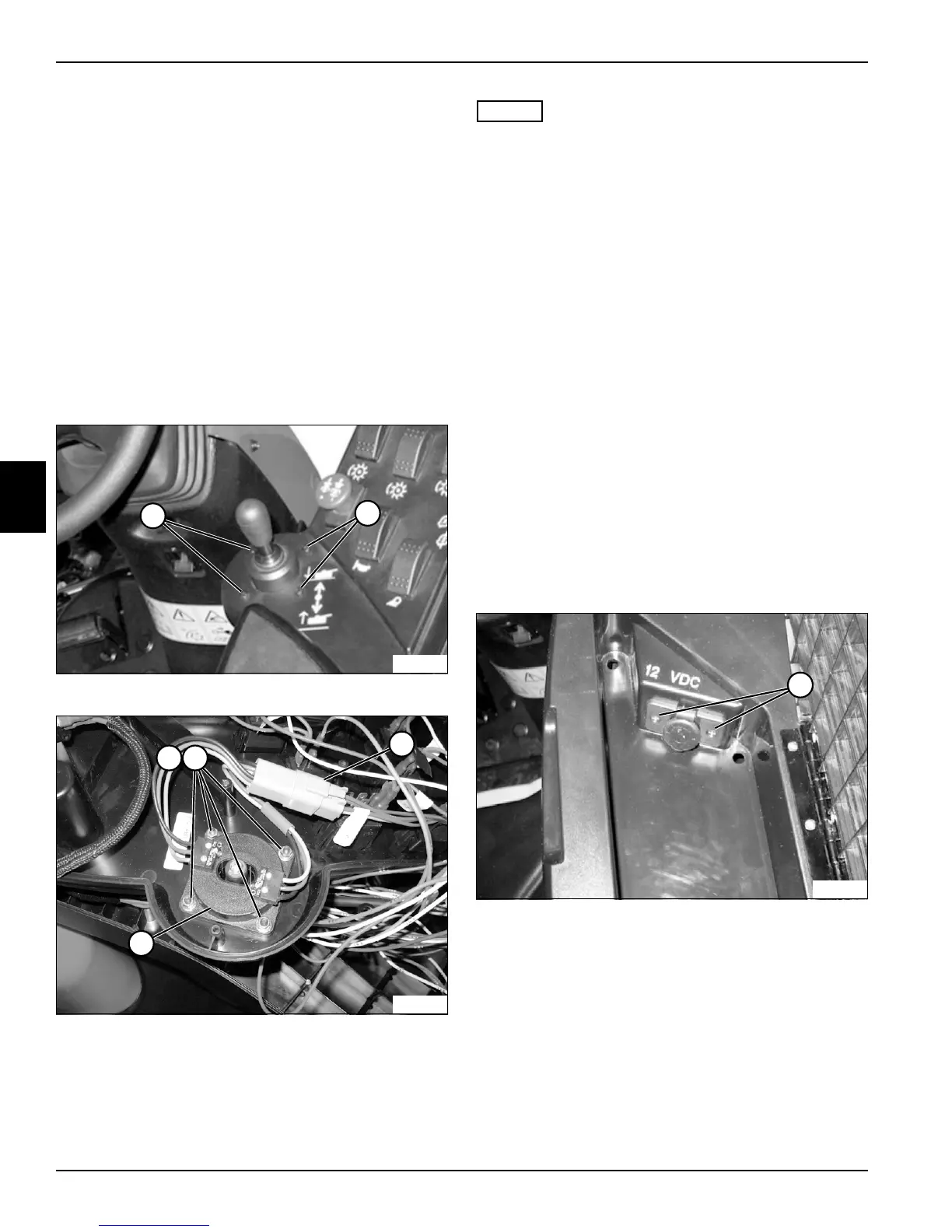
Raise/Lower Switch Assembly
Removal and Installation
See Figures 4-135 and 4-136.
1. Park the mower safely. (See “Park Mower Safely” on
page 1-6.)
2. Remove instrument panel. (See “Instrument Panel”
on page 4-151.)
Figure 4-135
Figure 4-136
NOTES
• For installation purposes, note orientation of the
raise/lower switch assembly.
• Label all wires before disconnecting to ensure correct
installation.
3. Remove four screws (1), nuts (2), and washers (3).
4. Tag and disconnect wire connector (4).
5. Remove raise/lower switch assembly (5).
Installation Notes
• Use new cable ties to secure wire connectors and
wire harness.
• Install raise/lower switch assembly by reversing the
order of removal.
12 VDC Accessory Plug
Removal and Installation
See Figures 4-137 and 4-138.
1. Park the mower safely. (See “Park Mower Safely” on
page 1-6.)
2. Remove instrument panel. (See “Instrument Panel”
on page 4-151.)
Figure 4-137
3. Remove two screws (1).
TN2331
1
1
TN2347
32
4
5
TN2348
1