CUTTING UNITS
4222983 Second Edition 6-31
6
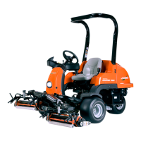
Figure 6-37
CAUTION
8. Remove reel (2) from frame (1).
Installation Notes
• Install reel assembly by reversing the order of
removal.
• Adjust reel bearing pre-load. (See “Reel Bearing
Pre-Load Adjustment” on page 6-18.)
• Adjust grass shield. (See “Grass Shield Adjustment”
on page 6-17.)
• Adjust bedknife-to-reel clearance. (See
“Bedknife-to-Reel Clearance Adjustment” on
page 6-16.)
• Check height-of-cut adjustment. (See “Height-of-Cut
(HOC) Adjustment” on page 6-17.)
• Level cutting unit. (See “Cutting Unit Leveling
Adjustment” on page 6-22.)
Front Roller
Removal and Installation
See Figure 6-38.
1. Park the mower safely. (See “Park Mower Safely” on
page 1-6.)
2. Raise cutting unit assembly with a suitable lifting
device and support the cutting unit frame to remove
weight from roller.
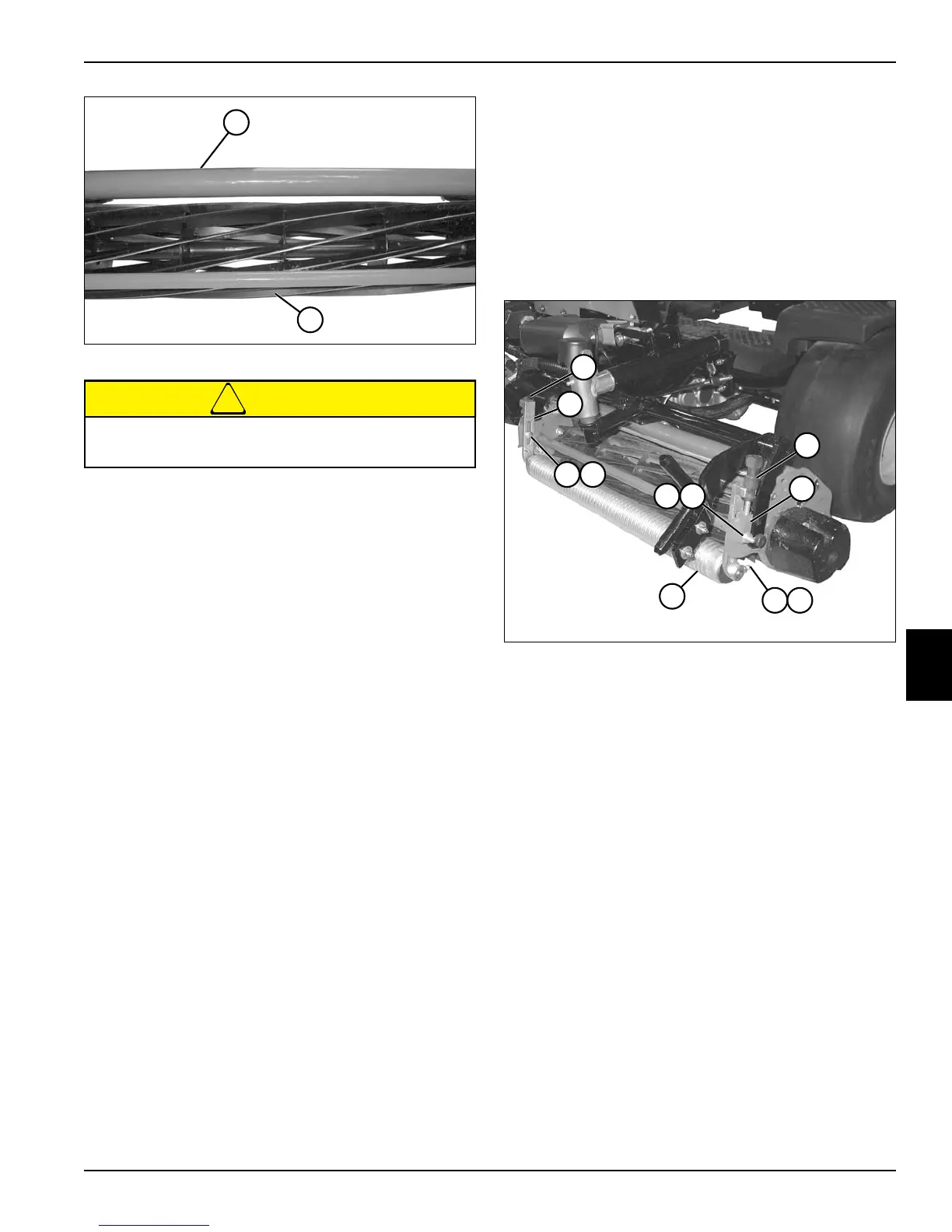
Figure 6-38
3. Remove nuts (3) and screws (4).
4. Remove adjuster knobs (1).
5. Remove adjuster brackets (2) and front roller (5) from
cutting unit.
6. Loosen jam nuts (6) and square head bolts (7) on
both sides of front roller (5).
7. Remove front roller (5) from adjuster brackets (2).
Installation Notes
• Install front roller by reversing the order of removal.
• Center the roller between the adjuster brackets
before tightening jam nuts and square head bolts.
• Align roller shaft flat with square head bolts before
tightening bolt on flat on each end of shaft.
• Check height-of-cut adjustment. (See “Height-of-Cut
(HOC) Adjustment” on page 6-17.)
To prevent personal injury and damage to the
cutting edges, handle the reel with extreme care.
TN2655
1
2
TN2649
6
1
4 3
5
1
2
2
4 3
7

 Loading...