ELECTRICAL
4222983 Second Edition 4-145
4
OLM
Removal and Installation
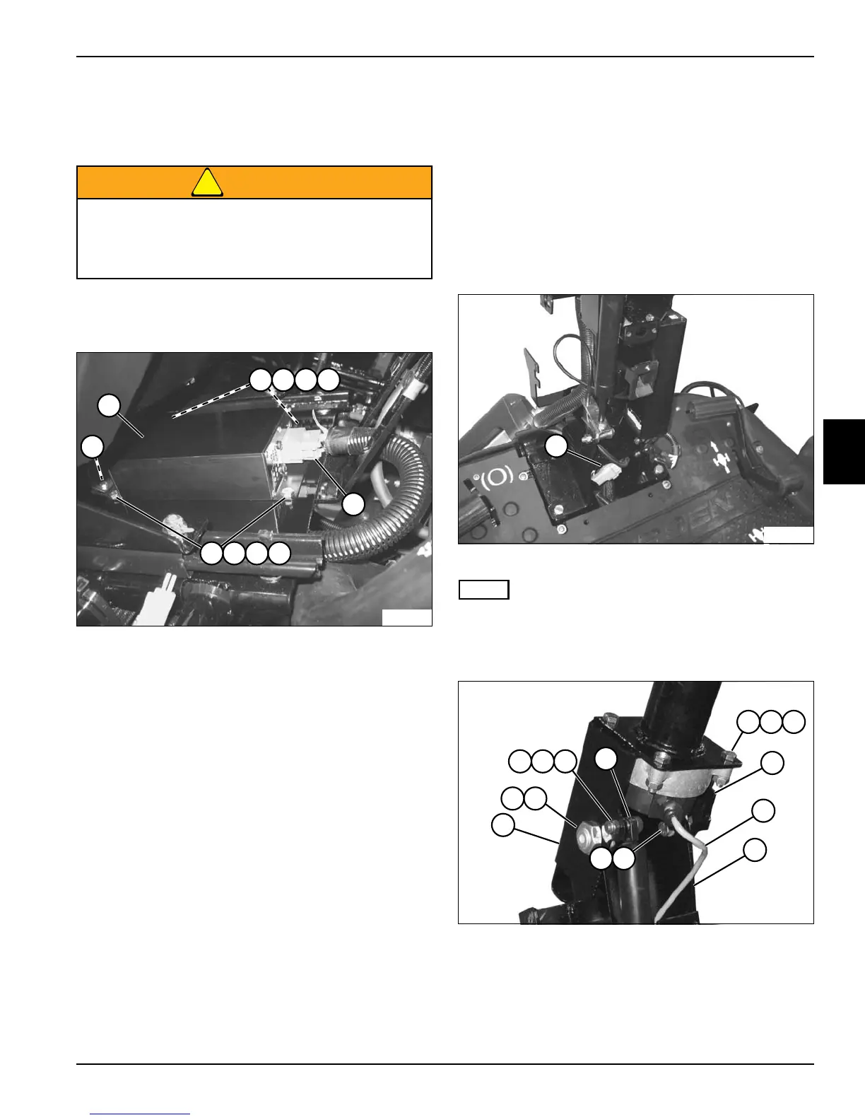
See Figure 4-114.
WARNING
1. Park the mower safely. (See “Park Mower Safely” on
page 1-6.)
Figure 4-114
2. Tag and disconnect OLM connector (5).
3. Support dome light assembly (6) and remove screws
(1), flat washers (2), lock washers (3), and nuts (4).
Secure dome light assembly (6) out of the way.
4. Remove OLM (7).
Installation Notes
• Install OLM by reversing the order of removal.
• Apply dielectric grease (Jacobsen PN 365422) to any
connectors removed.
Steering Wheel Input Device
Removal and Installation
See Figures 4-115 and 4-116.
1. Park the mower safely. (See “Park Mower Safely” on
page 1-6.)
2. Remove covers. (See “Front Cover” on page 7-16
and “Rear Cover” on page 7-16.)
3. Remove steering wheel. (See “Steering Wheel” on
page 7-14.)
Figure 4-115
NOTE
Label all wires before disconnecting to ensure correct
installation.
4. Disconnect wire connector (1).
Figure 4-116
5. Carefully guide the wire harness (10) up and through
the steering column weldment (11).
6. Remove screw (2), spacer (3), and nut (4) and
disconnect gas spring (5) from upper steering
column weldment (14).
Be sure that the key switch is off, all electrical
accessories are turned off, and the 12-volt and
48-volt power connectors are disconnected
before starting work on machine.
5
7
TN2419
4321
4321
6
TN2393
1
TN2390
16
13
876
10
11
432
5
9
14
15
12