7-12 4222983 Second Edition
ACCESSORIES AND MISCELLANEOUS REPAIR
7
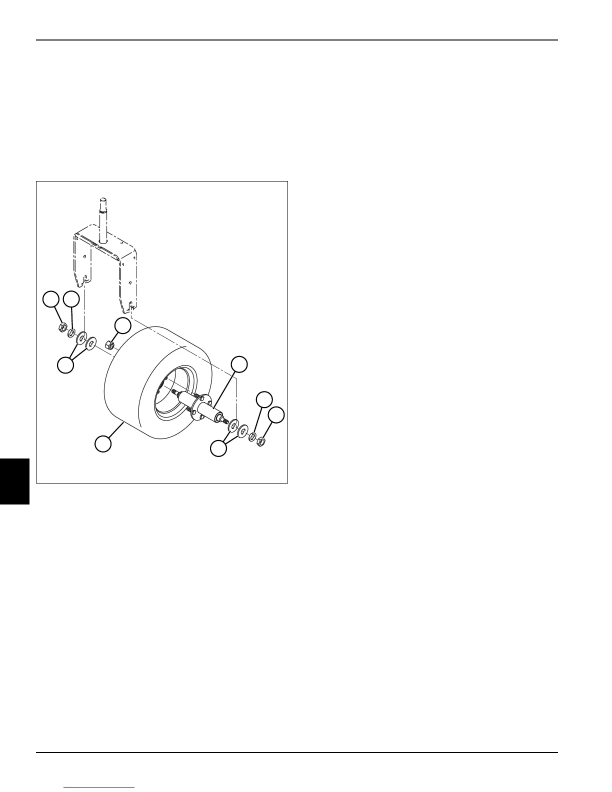
Rear Wheel and Axle Assembly
Removal and Installation
See Figure 7-20.
1. Park the mower safely. (See “Park Mower Safely” on
page 1-6.)
2. Remove rear fender. (See “Rear Fender” on
page 7-11.)
Figure 7-20
3. Raise and support rear of machine with jackstands.
4. Support the rear wheel and axle assembly with a
suitable lifting device.
5. Remove nuts (1), lock washers (2), and flat washers
(5).
6. Remove the rear wheel and axle assembly from the
machine.
7. Remove four lug nuts (3).
8. Remove rear axle assembly (4) from wheel (6).
9. Inspect tread area for tears or other damage.
10. Replace tire if damage is excessive.
Installation Notes
• Inspect and clean any rust from rear axle assembly
(4) or wheel mounting area.
• Install rear wheel and axle assembly by reversing the
order of removal.
• Tighten lug nuts (6) to 80 lb-ft (108.5 N·m) using an
alter nating pattern.
• Tighten rear axle assembly mounting nuts (1) to 150
lb-ft (203 N·m).
• Set tire pressure to 20 psi (1.38 bar).
TN2400
TN2400
2
1
3
2
5
1
4
5
6