•
Verify that the site meets the requirements described in “Site Preparation Checklist
for EX2200 Switches” on page 61.
•
Place the desk in its permanent location, allowing adequate clearance for airflow and
maintenance, and secure it to the building structure.
•
Read “General Safety Guidelines and Warnings” on page 169, with particular attention
to “Chassis Lifting Guidelines for EX2200 Switches” on page 183.
NOTE: Do not block the vents on the top of the EX2200-C switches. Doing
this can lead to overheating of the switch chassis.
Ensure that you have the following parts and tools available:
•
4 rubber feet to stabilize the chassis on the a desk or other level surface (provided in
the accessory box in the switch carton)
•
1 cable guard and 3 number-8 Phillips truss-head screws (optional and separately
orderable) to secure the cable guard to the EX2200-C switch
•
1 standard cable lock (optional and separately orderable) to secure the EX2200-C
switch models only from theft by connecting the cable to the security slots on the
switch
To mount a switch on a desk or other level surface:
1. Remove the switch from the shipping carton (see “Unpacking an EX2200 Switch” on
page 86).
2. Turn the chassis upside down on the desk or the level surface where you intend to
mount the switch.
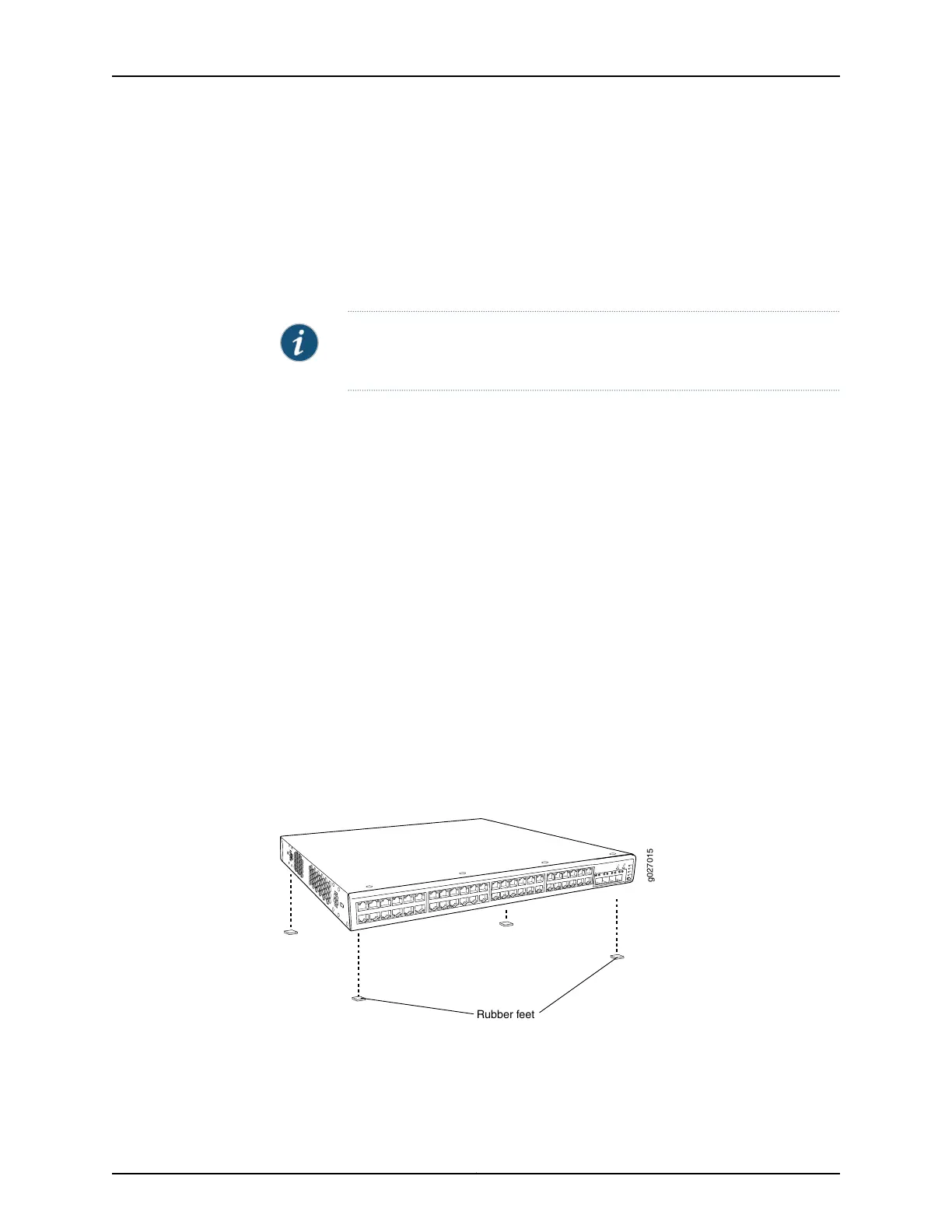
3. Attach the rubber feet to the bottom of the chassis, as shown in Figure 21 on page 90.
4. Turn the chassis right side up on the desk or the level surface.
Figure 21: Attaching Rubber Feet to a Switch Chassis
Rubber feet
g027015
SYS
ALM
SPD
DX
POE
EN
5. (Optional; applies only to EX2200-C models) Attach the cable guard to protect cable
connections:
a. Use the 3 truss-head screws toattach the cable guard to the bottom of the chassis.
Copyright © 2015, Juniper Networks, Inc.90
Complete Hardware Guide for EX2200 Ethernet Switches