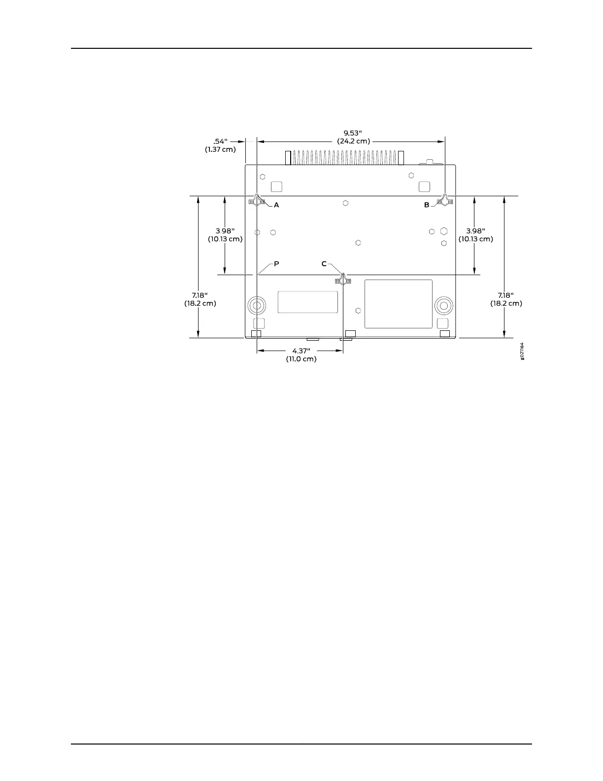
Figure 37: Measurements for Installing Mounting Screws for the EX2200-C
Switch
a. Drill hole A and install a mounting screw.
b. Drill hole B 9.53 in. (24.2 cm) on a level line from hole A and install a mounting
screw.
c. Mark a point P 3.98 in. (10.13 cm) on a plumb line down from hole A.
d. From point P 4.37 in. (11.0 cm) on a level line drill hole C and install a mounting
screw.
3. Tighten the screws only part way in, leaving about 1/4 in. (6 mm) distance between
the head of the screw and the wall.
4. Mount the switch on the mounting screws facing front panel downwards, and slide it
downward until it locks in place as shown in Figure 38 on page 108.
107Copyright © 2015, Juniper Networks, Inc.
Chapter 8: Installing the Switch