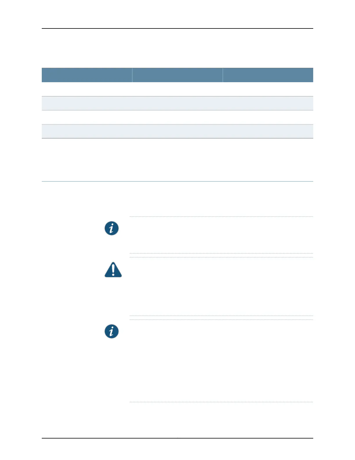
Table 16: Management Port Connector Pinout Information for EX2200 Switches
DescriptionSignalPin
Transmit/receive data pair 1TRP1+1
Transmit/receive data pair 1TRP1-2
Transmit/receive data pair 2TRP2+3
Transmit/receive data pair 2TRP2-6
Related
Documentation
See EX2200 Switches Hardware Overview on page 3 for port location.•
• Connecting a Switch to a Network for Out-of-Band Management on page 127
Pluggable Transceivers Supported on EX2200 Switches
Uplink ports and dual-purpose uplink ports on the front panel in EX2200 switches support
SFP transceivers. This topic describes the optical interfaces supported for those
transceivers. It also lists the copper interface supported for the SFP transceivers.
NOTE: We recommend that you use only optical transceivers and optical
connectors purchased from Juniper Networks with your Juniper Networks
device.
CAUTION: If you are having a problem running a Juniper Networks device
that is using a third-party optic or cable, the Juniper Networks Technical
Assistance Center (JTAC) can help you diagnose the source of the problem.
Your JTAC engineer might recommend that you check the third-party optic
or cable and potentially replace it with an equivalent Juniper Networks optic
or cable that is qualified for the device.
NOTE: EX2200-C switches ensure normal operationin the temperaturerange
30º F (0º C) through 104º F (40º C) at altitudes up to 1,524 m (5,000 ft).
In the followingconditions,use extended temperature rangeSFPswhen fiber
uplinks are used:
•
In the temperature range 104° F through 113° F (40° C up to 45° C) at
altitudes up to 1,524 m (5,000 ft)
•
In the temperature range 95° F through 113° F (35° C up to 45° C) at
altitudes above 1,524 m (5,000 ft) up to 3,048 m (10,000 ft)
Copyright © 2015, Juniper Networks, Inc.26
Complete Hardware Guide for EX2200 Ethernet Switches