Ensure that you have the following parts and tools available:
•
DC power source cables (14 AWG) with ring lug (Molex 0190700067 or equivalent)
(not provided) attached to them by a licensed electrician
•
Phillips (+) screwdriver, number 2
To connect DC power to the switch:
1. Ensure that the input circuit breaker is open so that the cable leads will not become
active while you are connecting DC power.
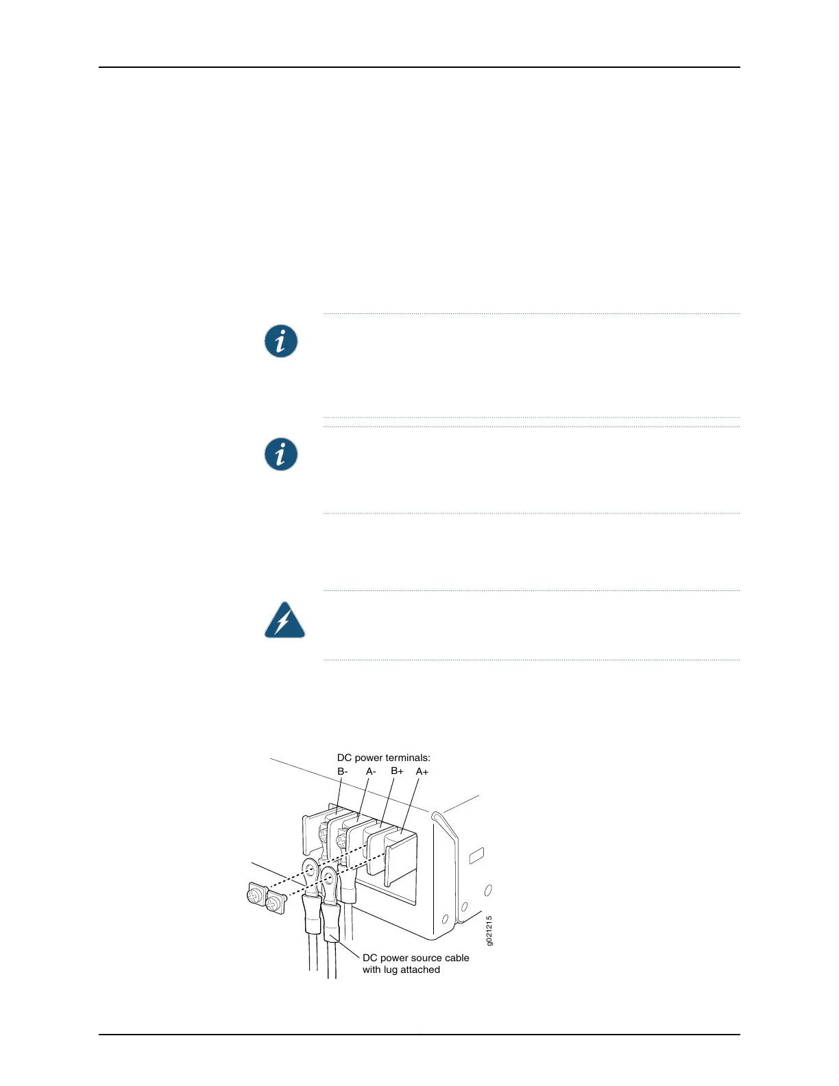
NOTE: The DC power supply in the switch has four terminals labeled A+,
B+, A–, and B– for connecting DC power source cables labeled
positive (+) and negative (–). The terminals are covered by a clear plastic
cover.
NOTE: The A+ and B+ terminals are referred to as +RTN and A– and B–
terminals arereferred to as –48 V in “DC Power Wiring SequenceWarning”
on page 208 and “DC Power Electrical Safety Guidelines” on page 203.
2. Grasp the plastic cover in the middle, gently flex it outwards, and pull it out. Save the
cover.
3. Remove the screws on the terminals using the screwdriver. Save the screws.
WARNING: Ensure that the power cables do not block access to switch
components or drape where people can trip on them.
4. Connect the power supply to the power sources. Secure power source cables to the
power supply by screwing the ring lugs attached to the cables to the appropriate
terminals by using the screw from the terminals (see Figure 49 on page 126).
Figure 49: Securing Ring Lugs to the Terminals on the DC Power Supply
g021215
A-
DC power source cable
with lug attached
B-
B+
A+
DC power terminals:
Copyright © 2015, Juniper Networks, Inc.126
Complete Hardware Guide for EX2200 Ethernet Switches