• Connecting Earth Ground to an EX Series Switch on page 117
Cooling System and Airflow in an EX2200 Switch
Thecoolingsystem in EX2200 switches, except EX2200-C, the compact, fanless models,
consists of two fans along the rear of the chassis that provide side-to-rear chassis cooling.
In the PoE models of these switches, there is an additional fan in the power supply.
In the EX2200-C switch the cooling is done by the vents on top and sides of the chassis
in non-PoE models and by heatsinks in PoE+ models. Do not block the vents on the
chassis. Doing this can lead to overheating of the switch chassis
This topic describes:
•
Airflow Direction in Non-PoE Models of EX2200 Switches, Except for the EX2200-C
Models on page 19
•
Airflow Direction in PoE Models of EX2200 switches, Except for the EX2200-C
Models on page 20
Airflow Direction in Non-PoE Models of EX2200 Switches, Except for the EX2200-C Models
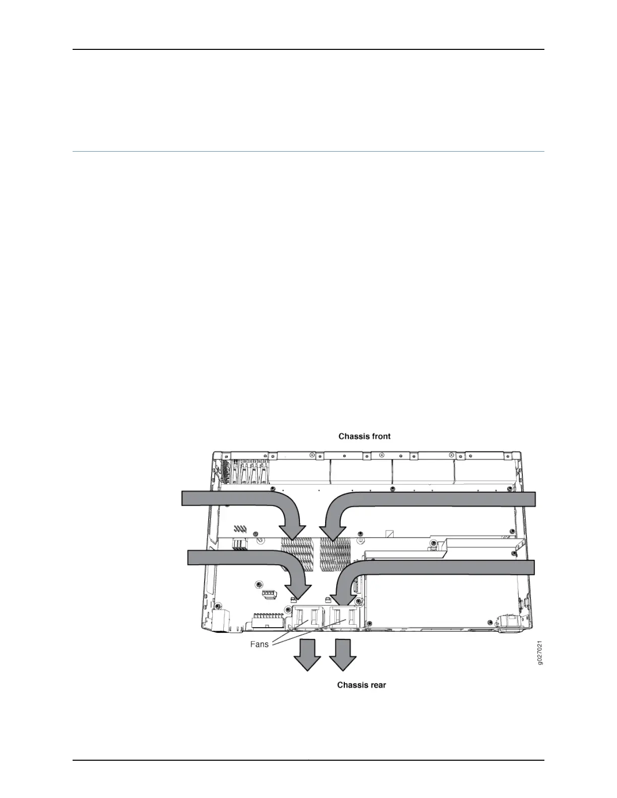
Figure 14 on page 19 shows the airflow in non-PoE models of EX2200 switches, except
for the EX2200-C models.
Figure 14: Airflow Through Non-PoE Models of EX2200 Switches Except
the EX2200-C Switch Model
19Copyright © 2015, Juniper Networks, Inc.
Chapter 2: Component Descriptions