Airflow Direction in PoE Models of EX2200 switches, Except for the EX2200-C Models
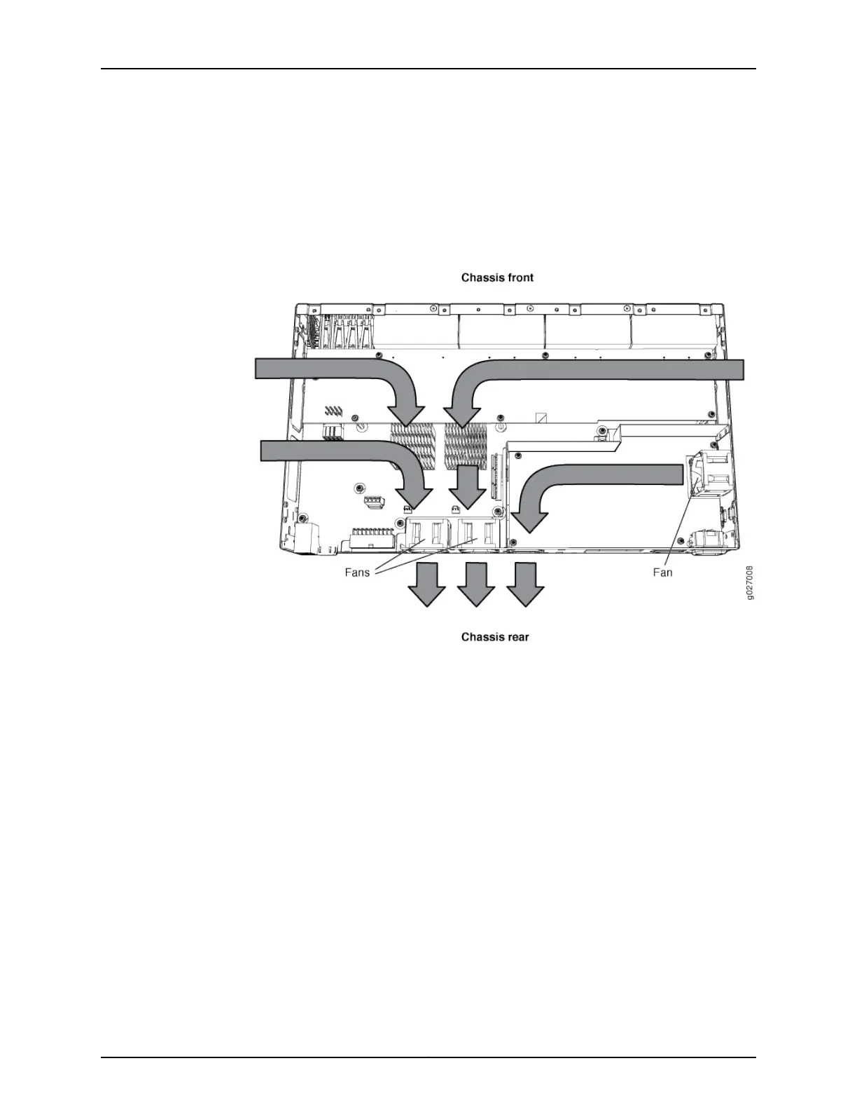
Figure 15 on page 20 shows the airflow in PoE models of EX2200 switches, except
EX2200-C models.
Figure 15: Airflow Through PoE Models of EX2200 Switches Except the
EX2200-C Switch Models
Under normal operating conditions, the fans operate at a moderate speed to reduce
noise. Temperature sensors in the chassis monitor the temperature within the chassis.
If any fan fails or if the temperature inside the chassis rises above the threshold, the
switch raises an alarm and all functioning fans operate at a higher speed than normal.
If the temperature inside the chassis rises above the threshold, the switch shuts down
automatically.
Related
Documentation
• EX2200 Switches Hardware Overview on page 3
• Chassis Status LEDs in EX2200 Switches on page 13
• Understanding Alarm Types and Severity Levels on EX Series Switches
• Prevention of Electrostatic Discharge Damage on page 198
Copyright © 2015, Juniper Networks, Inc.20
Complete Hardware Guide for EX2200 Ethernet Switches