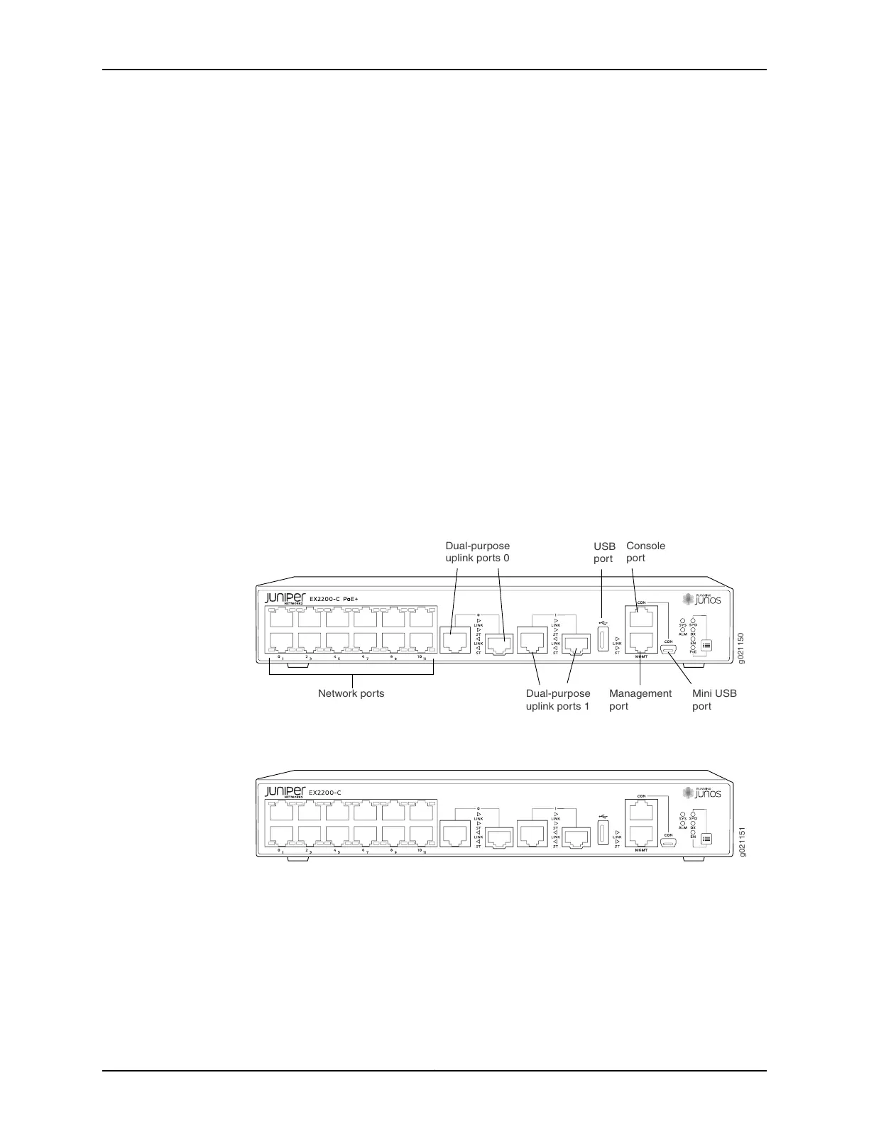
•
12 10/100/1000BASE-T Ethernet ports, (non-PoE) in EX2200-C-12T
•
12 10/100/1000BASE-T Ethernet ports, (PoE+) in EX2200-C-12P
•
2 built-in dual-purpose uplink ports, each of which includes one 10/100/1000 RJ-45
Ethernet port and one SFP port
•
1 USB port
•
1 Mini-USB console port
•
1 RJ-45 console port
•
1 Management Ethernet port
•
2 chassis status LEDs
•
4 port status mode LEDs in PoE+ and 3 port status mode LEDs in non-PoE
•
Mode button
Figure 3 on page 7 shows the front panel of an EX2200-C switch with 12 Gigabit Ethernet
PoE+ ports and Figure 4 on page 7 shows the front panel of an EX2200-C switch with
12 Gigabit Ethernet non-PoE ports.
Figure 3: Front Panel of an EX2200-C Switch with 12 Gigabit Ethernet
Ports (PoE+)
g021150
Network ports
Dual-purpose
uplink ports 0
Dual-purpose
uplink ports 1
Console
port
USB
port
Mini USB
port
Management
port
Figure 4: Front Panel of an EX2200-C Switch with 12 Gigabit Ethernet
Ports (non-PoE)
Rear Panel of an EX2200 Switch
The rear panel of the EX2200 switch except the EX2200-C switch models consists of
the following components:
•
Management Ethernet port
•
USB port
7Copyright © 2015, Juniper Networks, Inc.
Chapter 1: EX2200 Switch Overview