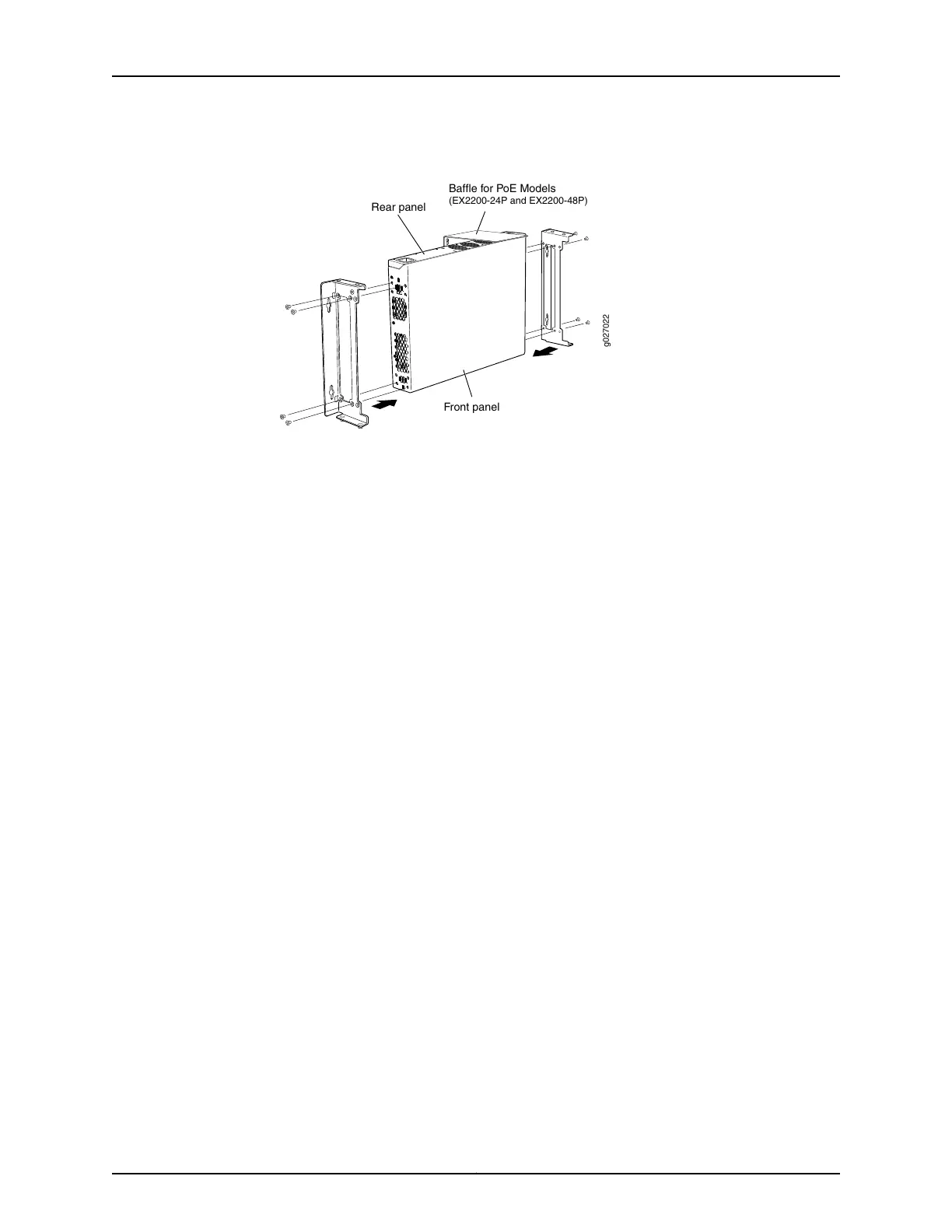
Figure 34: Attaching Wall-Mount Brackets to a Switch Chassis
g027022
Front panel
Rear panel
Baffle for PoE Models
(EX2200-24P and EX2200-48P)
3. If you are mounting two switches together, align the second switch on top of the first
and attach it to the mounting brackets using two additional wall-mount bracket
screws on each side. (Figure 36 on page 105 shows two aligned switches.)
4. Install four mounting screws in the wall for the wall-mount brackets (and two more
for the baffle if you are installing a switch that supports PoE) as shown in
Figure 35 on page 105:
•
Use hollow wall anchors rated to support up to 75 lb (34 kg) if you are not inserting
the mounting screws directly into wall studs.
•
Turn the screws only part way in, leaving about 1/4 in. (6 mm) distance between
the head of the screw and the wall.
a. Install screw A.
b. Install screw B 18.68 in. (47.4 cm) from screw A on a level line.
c. Install screw C 5.98 in. (15.2 cm) on a plumb line down from screw A and screw D
5.98 in. down from screw B.
d. For PoE models, install screw E 2.76 in. (7 cm) up from and 8.32 in. (21.1 cm) to the
right of screw A.
e. For PoE models, install screw F 4.49 in. (11.4 cm) to the right of screw E.
Copyright © 2015, Juniper Networks, Inc.104
Complete Hardware Guide for EX2200 Ethernet Switches