the combined weight of two fully loaded chassis. Insert the screws into wall studs
wherever possible to provide added support for the chassis.
Use the wall-mount kit from Juniper Networks to mount the switch on a wall. The
wall-mount kit is not part of the standard package and must be ordered separately.
Related
Documentation
Clearance Requirements for Airflow and Hardware Maintenance for EX2200 Switches
on page 74
•
• Wall-Mounting Warnings for EX2200 Switches on page 189
• Mounting an EX2200 Switch on a Desk or Other Level Surface on page 89
• Mounting an EX2200 Switch on a Wall on page 102
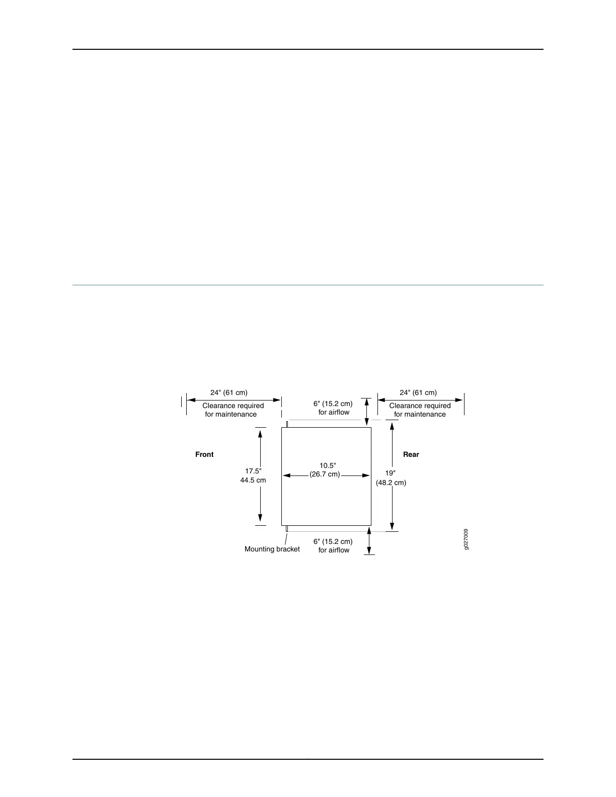
Clearance Requirements for Airflow and Hardware Maintenance for EX2200 Switches
When planning the site for installing an EX2200 switch, you must allow sufficient
clearance around the installed switch. Figure 16 on page 74 shows the clearance
requirement for EX2200 switches except the EX2200-C switch models.
Figure 17 on page 75 shows the clearance requirement for the EX2200-C switch models.
Figure 16: Clearance Requirements for Airflow and Hardware Maintenance
for EX2200 Switches Except EX2200-C Switch Models
g027009
Mounting bracket
6" (15.2 cm)
for airflow
Rear
Front
17.5"
44.5 cm
10.5"
(26.7 cm)
Clearance requiredClearance required
for maintenancefor maintenance
24" (61 cm) 24" (61 cm)
6" (15.2 cm)
for airflow
19"
(48.2 cm)
Copyright © 2015, Juniper Networks, Inc.74
Complete Hardware Guide for EX2200 Ethernet Switches