Chapter 8: Defining Study Setups
ValProbe RT User Manual 76
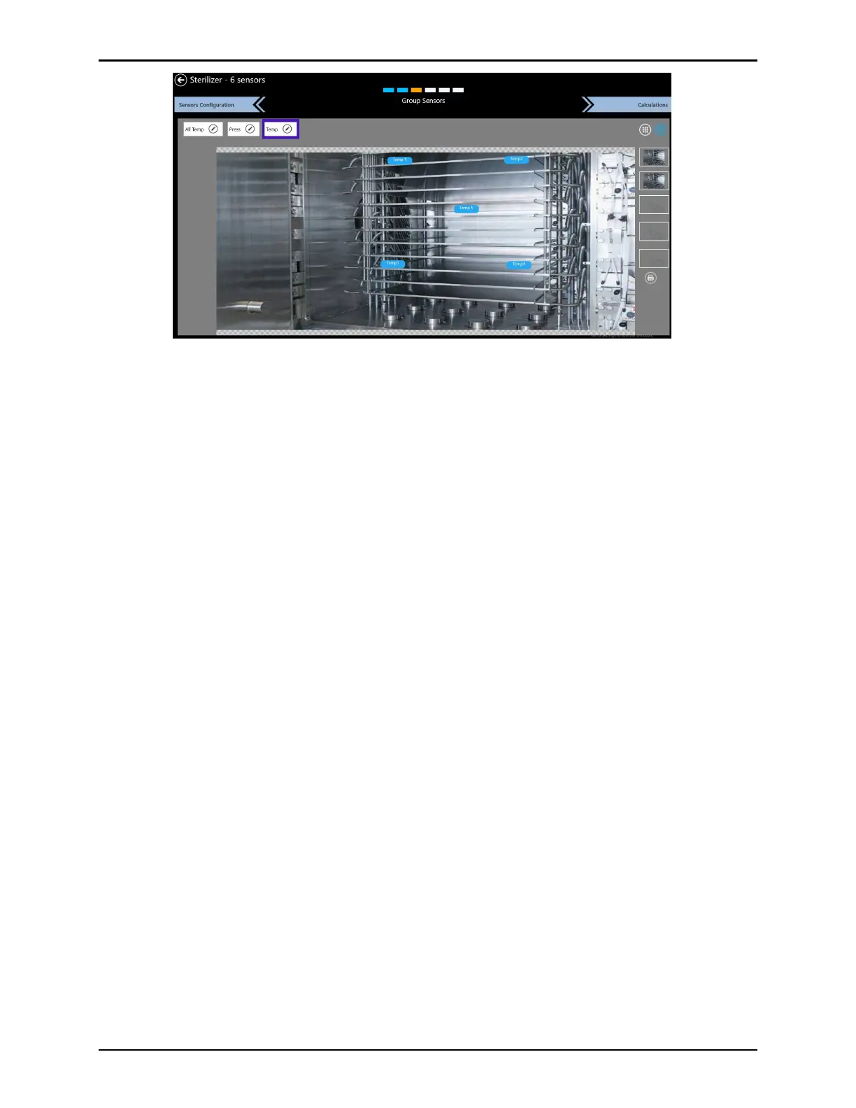
Figure 100: Wiring Layout Diagram
Using the wiring layout diagram, define up to five pictures as a background when positioning
sensors. Select a picture frame on the right side of the screen and load a picture from a file
using the Pen icon or Camera icon to take a picture with the built-in camera. Use the Trash
icon to delete pictures.
Note: Take pictures by selecting the Camera icon through the device camera. Ensure that
the software can access the camera. The picture can be taken by pressing the camera
icon through the device camera.
Sensor tags are movable, via drag and drop, to a position reflecting their position on the asset.
Use the Printer button to export the Wiring diagram into a .pdf.
For every group, select a picture and a sensor position, then save it along with the setup. The
wiring diagram is printed from the Wiring Layout screen or as a part of the Setup report directly
from the Asset Details screen. The wiring diagram is used in Layout View during Qualification
to provide live data.
To clear a sensor, select the sensor label and then select Clear Sensor.
When finished, select Calculations to proceed to the Calculations screen.