218 N9030B PXA Signal Analyzer Service Guide
Front End Control Troubleshooting
A15 Front End Control Assembly Troubleshooting
Oscilloscope Test
Measurements can be made to verify the current logic is getting to the
appropriate switch from the A15. In order to perform this measurement, the
outer cover and chassis RF bracket on the right hand side of the instrument
must be removed. Refer to Chapter 16, “Assembly Replacement Procedures”,
on page 429 for the removal procedures.
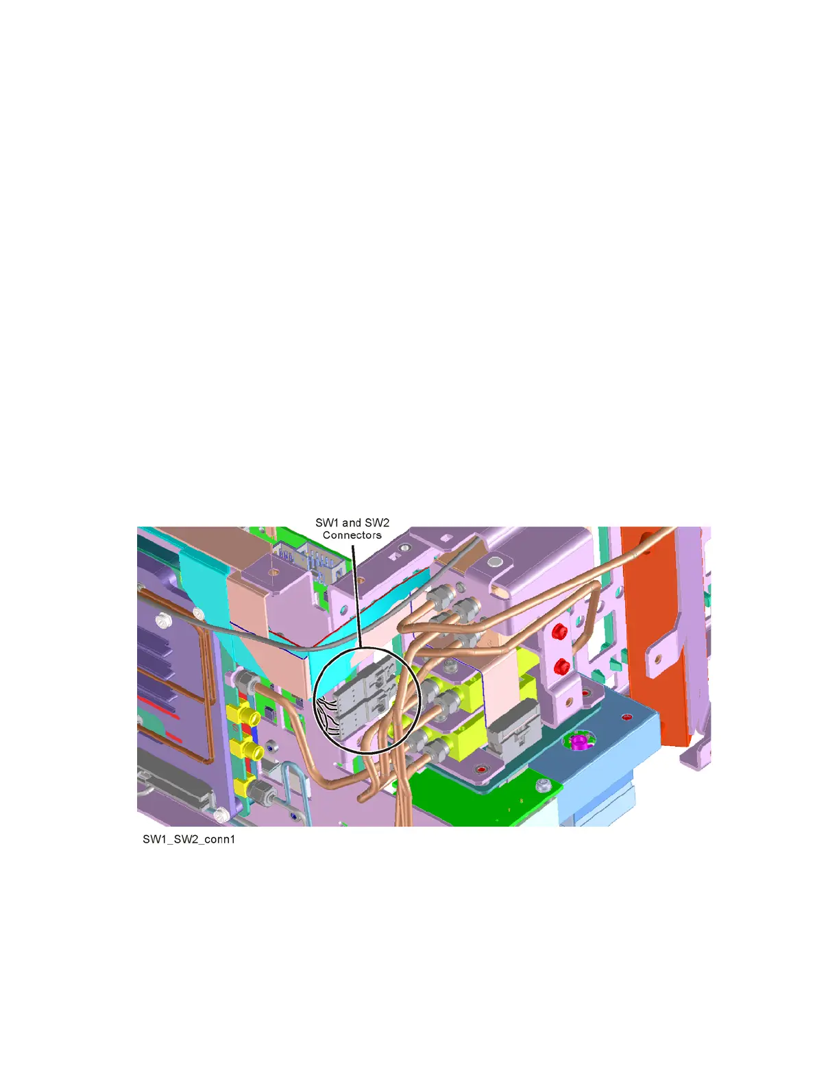
Figure 6-5, Figure 6-6, and Figure 6-7 illustrate the measurement location
where the oscilloscope probe should be used to measure the logic. There are
two connector bodies with three wires each. On one connector, the three wires
are green, black and orange. On the other connector, the three wires are green,
black, and yellow. On each connector, black is ground.
On analyzers with Option 508, 513, and 526, both connectors are used; one
connects to SW1 and the other to SW2. It does not matter which connector
connects to which switch. Both connectors are programmed to behave
identically.
However, on analyzers with Option 544 and 550, only the green, black, yellow
connector is used to control SW4.
Figure 6-5 SW1 and SW2 Connector Location (Option 508, 513, and 526)