N9030B PXA Signal Analyzer Service Guide 537
Assembly Replacement Procedures
Input Connector Assembly
Input Connector Assembly
Removal
1. Remove the instrument outer case. Refer to the Instrument Outer Case
removal procedure.
2. Remove the Front Frame Assembly. Refer to the Front Frame Assembly
removal procedure.
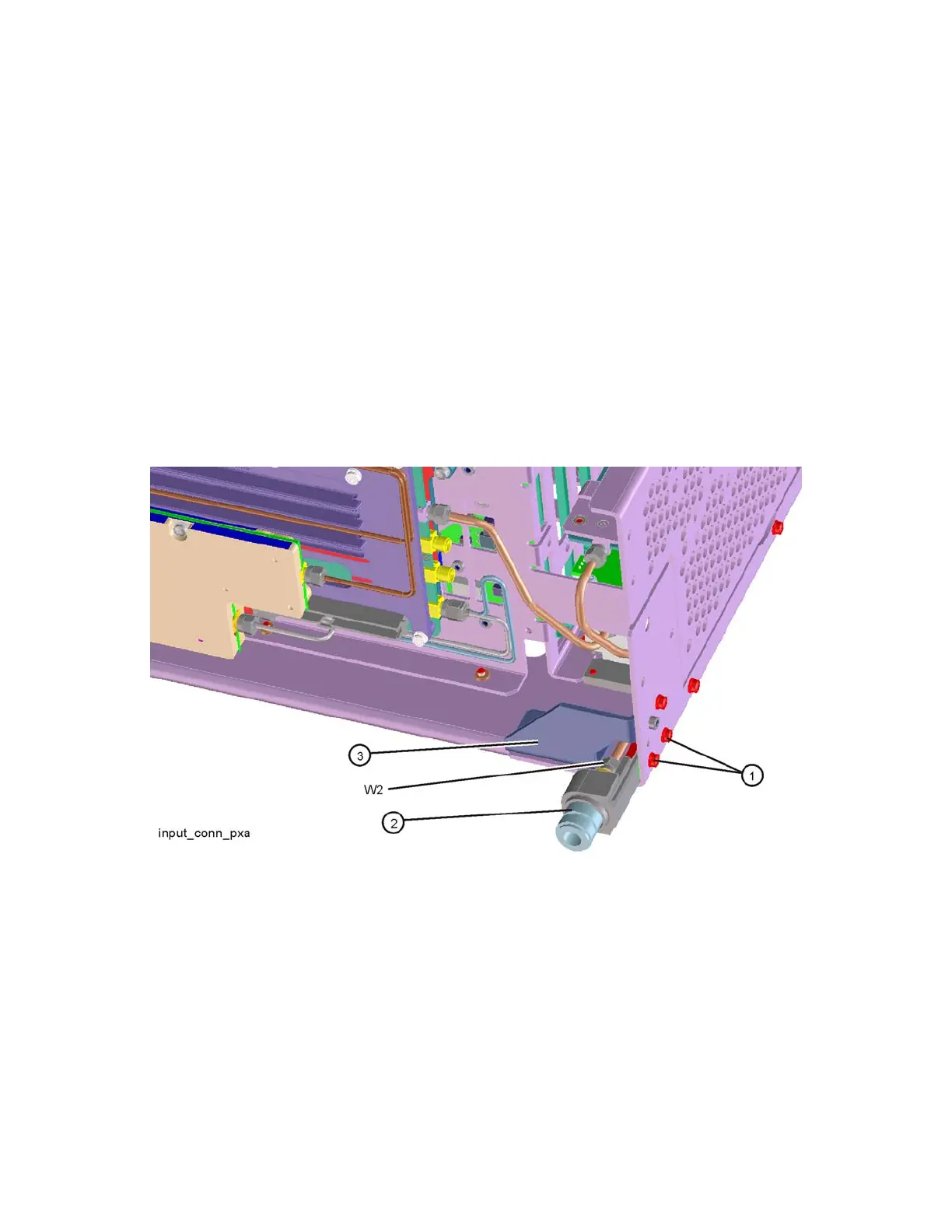
3. Refer to Figure 16-97. Disconnect the semi-rigid cable W2 from the Input
Connector Assembly.
Figure 16-97 Input Connector Assembly Removal
4. Remove the two screws (1) (0515-0372) that attach the Input Connector
Assembly to the chassis. The connector assembly can now be lifted from
the chassis.
Replacement
1. Refer to Figure 16-97. Place the Input Connector Assembly into position in
the chassis. Replace the two screws (1) (0515-0372) to attach the Input
Connector Assembly to the chassis. Torque to 9 inch-pounds.