N9030B PXA Signal Analyzer Service Guide 443
Assembly Replacement Procedures
RF Area (Options 503, 508, 513, 526)
Low Band Switch
Removal
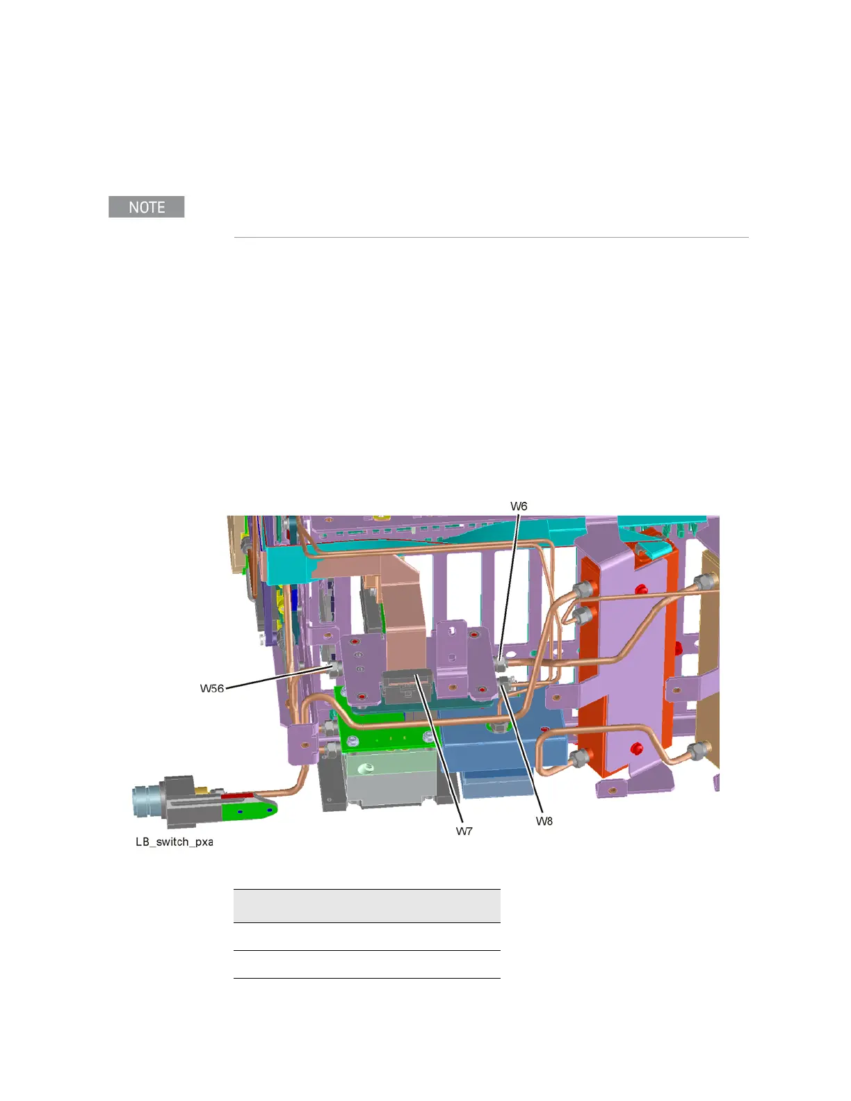
1. Refer to Figure 16-9. Remove the ribbon cable W7.
2. Remove the semi-rigid cables W6, W8, and W56 using the 5/16 inch
wrench. W6 and W56 are only present on analyzers without Option MPB
and/or LNP. If either of these options are present, the equivalent cables
would be W52 (for W6) and W54 (for W56).
3. Refer to Figure 16-10. Remove the two screws (2) (0515-0372) using the
T-10 driver. The low band switch (1) can now be removed from the
chassis.
4. Refer to Figure 16-11. To separate the switch from the bracket, remove the
four screws (3) (0515-0372) using the T-10 driver.
Figure 16-9 Low Band Switch Cable Removal
If the analyzer has hardware for Options MPB and LNP installed, perform the removal procedure
for Options MPB and LNP first.
Table 16-4
Item Keysight Part Number
W6 N9020-20024
W8 N9020-20101