N9030B PXA Signal Analyzer Service Guide 509
Assembly Replacement Procedures
Midplane Board Assembly
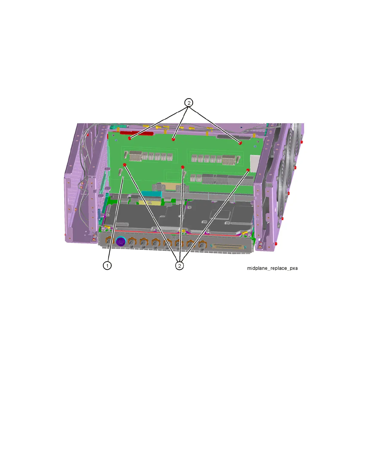
7. Refer to Figure 16-76. Remove the six screws (2) (0515-0375) attaching
the midplane board assembly (1) to the midplane bracket. The midplane
board assembly can now be pulled up from the chassis by use of the
ejectors.
Figure 16-76 Midplane Board Assembly Removal
Midplane Board Replacement
1. Refer to Figure 16-76. Install the midplane assembly into the chassis using
the ejectors and attach to the midplane bracket using the six screws
(0515-0375) removed earlier. Torque to 9 inch-pounds.
2. Replace the power supply assembly. Refer to the Power Supply Assembly
replacement procedure.
3. Replace the rear panel. Refer to the Rear Panel replacement procedure.
4. Replace the processor assembly. Refer to the CPU Assembly replacement
procedure.
5. Replace the top brace. Refer to the Top Brace and Power Supply Bracket
replacement procedure.
6. Replace the instrument outer case. Refer to the Instrument Outer Case
replacement procedure.